Antenna Design Software "YO"

[The last renewal of this page: December 21, 2009]
0. as a Preface...
The article that I put here in this page was written on Janurary in 1997, but after that, O/S for PC had been changed into Windows while the software I had introduced here works only on PC-DOS. Therefore, I let this article throw in the trashbox of this forum (Under half of the sub-menu) for a long time.
However, recently, I happened to find that it actually works perfectly even on a Windows XP, and therefore I decided let it revive again here.
This software written for a PC-DOS used work well on a DOS-window of Windows 95, but it never worked on a DOS-window on Windows 98 nor at DOS-Prompt of Windows XP. I don't understand why, but I happened to find that it got started and woked perfectly when I tried to click the excutable file (YO.EXE) at Explorer of Windows XP the other day! (It is absolutely unbelievable. But it works, really! That's good enough, isn't it?)
Well, Okay, then why should I use an old YO now?
That is because YO works much better than any other current windows' software for antenna design as far as I experienced, considering its functions such as the user interface (an interface which is reflected by user's intention "How it comes if it were..."), quick actions, handiness, speed, number of times of simulation, factors and conditions available for a simulation, etc. It may be my own taste, but I do believe that the YO is the best and an excellent antenna design software.
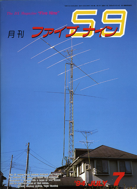
The below picture shows a PC-DOS PC runs YO. It may be hard to find a person who has this type of PC by now.
I happend to try one thing using Explorer on Windows XP...
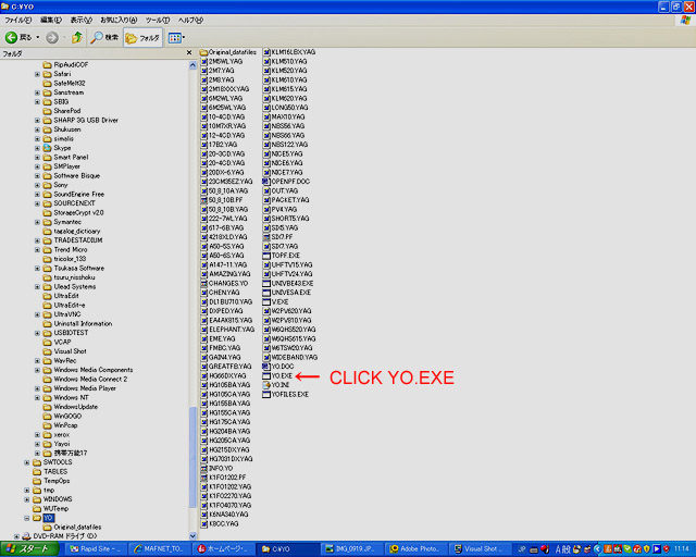
To my surprising, Yo started to run!!
It's incredible, really! Tank you so much for letting me back to use YO again for a long time from now and on.
[Notice]
I really do not know how the designer K6STI is doing now. I can not find any information about him on the internet, so I think it might be difficult to get this software now. Only way to get it could be ask someone who owns it already, I do not know. But I can say it worth doing a lot of effor to get one.
[The last renewal of this page (from this point forward): Januray 26, 1997]
1. Design antenna with computer
When I designed and bult a 7 element Yagi with 15meter(50foot) boom for
18MHz using "YO" by K6STI several years ago, there still were very few who
used to challenge computer design of antenna. As a matter of facts, when
I wrote an article regarding computer design with the YO in a hamradio
magazine, there came a lot of reactions and questions about it to me.
Now, I guess the thing is popular, and many hams are using that method
everywhere.
I had been troubled and confused a lot with fighting agaist my very first
7elment Yagi for 18MHz, doing a lot of cuts-and-tries to get a good
performance. I started with a 3element Yagi, then I added a element one
by one in every two or three weeks extending a boom pipe, like a 4element
Yagi, a 5element Yagi, a 6element Yagi, and finally a 7element Yagi.
However, I could not get front gain more after the 4 element Yagi even I
added more elements to it. Trying to shorten or extend the elements and
changing element spacing got me fall in hell from which I could never be
survived.(Hi Hi)
I was doing thoughtless, then. After having simulation with YO, it is
obvious that I was stupid. Yagi antenna is very delicate, and even on
18MHz, only one centimeter change of a element or the element spacing
results a big loss of its front gain, beam pattern, or the front back
ratio. There is no way to get a proper tuning by just doing cuts-and-
tries. I will never be back to build an antenna without this sort of
usueful software. ( You may have a resolusion by cuts-and-tries on a
cubicalquad antenna, as their resonation is generally really broad. Yagi
is differente. )
2. The YO/Yagi Optimizer
There should be some more softwares which works as well as YO now, but
I have been using the YO written by K6STI since 1992.( The main reason is
that I do not have enough money to buy other software!) I ordered the
YO simply sending a FAX to him, paying with credit card, and was surprized
the software came here only 4 days later by air. The software works under
DOS, not Windows, however, it works really fast and quickly under simple
DOS platform. ( I guess I originaly paid US$50.00 for this. Now I am
using the version 6.5.)
The YO consists with follwoing files;
YO.EXE Yagi Optimizer program
UNIVESA.EXE Universal VESA Video BIOS Extension (freeware)
UNIVBE43.EXE Universal VESA Video BIOS Extension (shareware)
V.EXE File viewer
TOPF.EXE Converts .PLT plot files to OpenPF plot files
YO.DOC YO documentation
OPENPF.DOC Documentation for the OpenPF plot-file standard
CHANGES.YO YO revisions
*.YAG Yagi files
The YO analizes and simulates considering many factors including
followings;
- Height of the antenna.
- Resonant Frequency.
- SWR.
- F/B Ratio.
- Boom Length and Diameter.
- Taper Schedule of each element.
- Materials of element.
- Matching Method for the feeding point.
- Shape and Size of the Mast Bracket.
It's a lot of fun just looking at the digits and antenna flat view change
and vary at real time as calculation is going on.
3. Example of the Simulation
Followings are real simulations on my 5element Yagi for 14MHz. I build
the antenna exactly as YO said, and put it up at 22meters heigh without
any tuning and test. I got pretty low SWR, less than 1 to 1.1 at both
edge of the band! Almost no reflected power is detected through out the
band! The beam pattern is almost the same as the simulation. Since the
same day that I put it up, I have been enjoying ragchews with overseas
stations with running just a barefoot.
Main page where the YO calculates and optimizes the antenna.
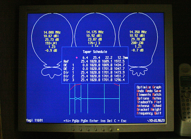
You can set the taper schedule of every element.
Graph for Front Gain, SWR, F/B Ratio, Impedance.
Horizontal Beam pattern(Azimuth Plane)
Vertical Beam pattern(Elevation Plane)
If you put up this antenna at 100meters(300feet) high,
Radiation angle would be as low as this!
Above graphic files (Originally they were in PCX format) were put out
directly from this software.
The YO also output a text file regarding the tapering conditions as below.
The top line in the list shows the diameter of each tubing, and lines
below shows the each length of the tubing. The most left row shows the
element sapacing.
5 element Yagi for JR1MAF
Height 22000.000
14.000 14.175 14.350 14.258 MHz
5 elements, millimeters
               22.5000   19.0000   16.0000   13.0000   10.0000    8.0000
      0.0000  950.0000  850.0000  850.0000 1605.0000 1265.5325    0.0000
   2026.3319  950.0000  850.0000  850.0000 1360.0000 1219.8965    0.0000
   3186.2268  950.0000  850.0000  850.0000 1356.0000 1194.1265    0.0000
   6746.4307  950.0000  850.0000  850.0000 1300.0000 1142.2227    0.0000
  12000.0000  950.0000  850.0000  850.0000 1270.0000  904.3046    0.0000
Hairpin Match should be: 8/150/500/5044.7/80
4. How you can contact with K6STI
Brian Beezley, K6STI
3532 Linda Vista Dr.
San Marcos, CA 92069
(619) 599-4962
0700-1800 Pacific Time
[Postscript 1] (Renewal: December 21, 2009)
I prepared a PDF file of my article "Modify a commercial made 7element Yagi for 18MHz using YO" in Monthly Five Nine magazine(July, 1994), as I introduced in the above article. I have more comments on YO there, so if you have more interest, please download it and take a look. (Written in Japanese)
Download
[Postscript 2] (Renewal: December 21, 2009)
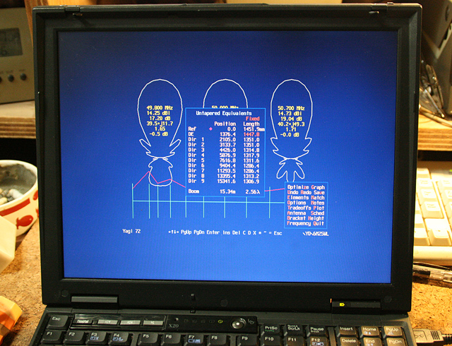
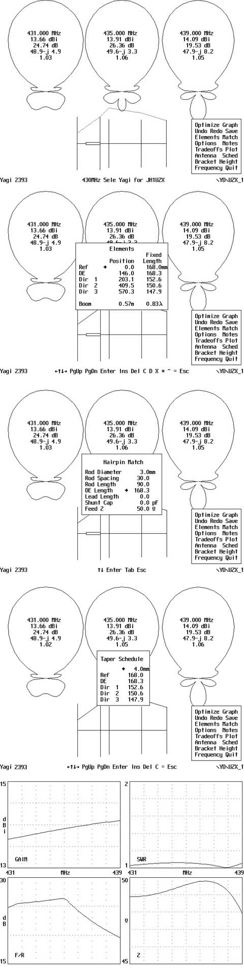
As YO has came back again with me on Windows XP, after a long time, I designed 5 element Yagi for 430MHz for my friend who tries to enjoy hamradio living in a apartment house. As I thought that it is a good opportunity to show you how it works, I hereby introduce some of the files being produced during the optimization.
There are many screens being displayed, but I pick up only few of them so that you can see all the basic data.?
As he is interested in an antenna with a low SWR through the band, I put the heaviest weight on SWR. He also wants a small antenna for his space problem, I reduced its boom length to 57cm.
I choosed a Hairpin-matching because it's easy to build. All the size of a Hairpin-matching system is displayed. I disregarded an effect of mast bracket. I designed it for 2mh above the ground.
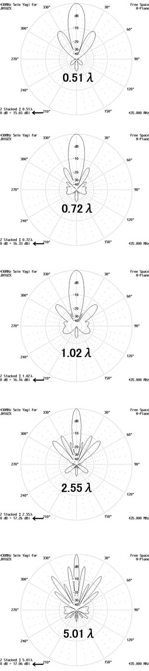
Next, I tried to see how the gain (see an arrow sign) and beam pattern will be changed as I stacked it.
20 stacked beam (Imposible, though...) shows a pattern just like a needle! You may lose a signal during a backrush of your rotor! A big difference between a sngle and 2 stacked. A single beam may not be the way to go.

Lastly, I tried to see what could be the best spacing between stacked antennas.
A 0.5 lambda is not good for gain and pattern both. Around 0.7 lambda seems to be the best choice with a simple beam pattern. Front gain itself comes to the maximum at around 2.5 lambda. Wider than that will break down the beam pattern in pieces...
 In case you hit this
page directly from a Search Engine, you can reach to all of the pages of MAFNET from Top Page
In case you hit this
page directly from a Search Engine, you can reach to all of the pages of MAFNET from Top Page