All tube 3.5-28MHz 100W SSB/CW Transceiver (MAFTR-38A)
- Built in 2011 -

[The last renewal of this page: Jan. 10, 2012]
It's a shame to tell you that I have no experience to generate SSB in the past 40 years of my history as a radio amateur, but I have been always interested in doing so. The other day, I finally completed building a line of AM/CW transmitter and receiver, and now, I have nothing else to choose other than SSB radios of my heart's desire for the next project.
There might be a theme to discuss about whether if you choose a transceiver or a transmitter. Well, I don't think that we need to list up the merits of transceiver such as a transceive operation, a cost-down due to the common use of the circuit, a space-saving, etc.
As the SSB transmission circuit does not have a multiply circuit to obtain a target frequency, it is hard to find a necessity to be a separate transmitter. So, I choosed a transceiver without any hesitation.
There might be another theme to discuss about whether if you choose a mechanical/crystal filter type generator or a PSN type generator.
In recent years, thanks to a development efforts of earnest amateurs, new types of PSN generator such as "All pass filter type PSN", "Poly-phased type PSN", etc. have been getting very popular to provide a super quality, which is an apparently different world from the old mechanical/crystal filter type generator.
However, I can not take a short cut to the expanded PSN, because I started from 1960's with all tube AM systems, and have been tracing what we have done forty to fifty years ago. On the other hand, it is true that there's so much waste of time and resource if I build two complete SSB transceiver set, one for a mechanical/crystal filter type generator, and the other one for a PSN type generator. So, I decided to build a transceiver to accept two generator units to be switched to choose. For the 1st step, I will complete the transceiver with only a crystal filter type generator. Later on, I will try to challange for expanded PSN generators to be mounted.
The next is the structure of hardware. As this is my first challenge to the SSB radio, an all band transceiver with two generators is something too much. In the beginning, aiming for a definite functioning, and considering future's growth for V/UHF, I thought I would separate it into two equipments at the bandpass filter, i.e., a part of exciter with VFO and a part of all band mixer with amplifire, to build them in different cabinets.
I thought that with this method, it is possible to modify or do version up for one of each separately, and must be a good idea for a begginer.
I therefore drew a separate block diagrams and circuit diagrams, one for exciter unit, and one for all band mixer with power amplifire.
However, after the much consideration, with a reversal idea, I reached to the conclusion that I would unite two parts into one, to form an all band transceiver with ideas as follows:
1. In my case, 99.9% of actual operations are on 14MHz.
2. Then a monoband transceiver for 14MHz would be nice, because it's easy to build and uniting two parts (Exciter, and Mixer & Amplifire) would not be much problem.
3. However, if in the future, when I feel that I rould like to get on other bands, a transverter could realize it but building another amplifire for 100W for a transverter sounds very uselessness, and is not the way to go.
4. Well, a compromise would be a monoband transceiver for 14MHz with a band switch and a space for coils are installed for growing up to be an all band transceiver later. In another word, "a 14MHz monoband transceiver to be able to modify to all band transceiver with a simple modification", or "an all band transceiver being wired only for 14MHz monoband transceiver".
5. It may sound there's little difference, but I'm sure that actually it'll be much easier considering the level adjustments for each stage for all bands, at least. Well, the idea is that there is a band switch which is not used being installed in a mono band transceiver, and the wiring for a mono band transceiver is done via the switch.
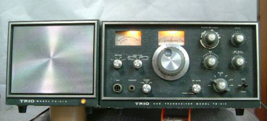
To determine the frequency compositions, I refered and compared the Japanese historical famous commercial made transceivers.
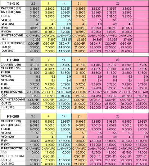
This is the frequency structure of old nice transceivers, YAESU FT-200, FT-400, and TRIO TS-510. (I excluded transceivers with a mechanical filter, becase I did not like 455KHz filters to avoid image heterodyne problems.)
FT-200 has a pre-mixed VFO with a very complicated heterodyne structure. It is designed to save heterodyne crystals, so depending on the band, it uses a plus heterodyne or minus heterodyne. As a result, dial starts either end of the scale from zero KHz, depdending on the band. That's too complicated and no comfortable!
The VFO of FT-400 oscilates 8MHz, and it's somewhat too high for stability. All the heterodynes are made with minus caliculation, and is not comfortable for me to caliculate them! hi hi.
TS-510 has a standard 5MHz VFO, and all the heterodynes are caliculated with plus! It's simple and nice!
So, I decided to use the frequency structure of TRIO TS-510.
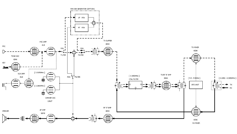
This is a block diagram for the portion of the exciter. As I initially intended to build two portions separated, like the Exciter and the All band mixer + Power amplifire, the diagram is also divided into two pages, sending and receiving the IF signal between 8.3 to 8.9MHz beween them. (This structure that is clearly separated into two parts without any interferences maybe also importante for the actuall installation.)
For the next project for PSN type SSB generator, a selector switch is installed to switch the generator between "Filter type" and "PSN type".
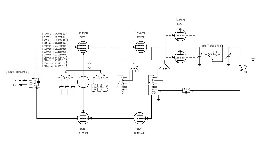
This is a block diagram for the portion of the all band mixer and power amplifire.
The frequency range will be from 3.5MHz to 28MHz including WARC bands. The transmitters that I built in the past were 10W output, but this time, it'll be 100W considering for the practical use.
It is wise to get a junk of TRIO TS-510 to which the frequency structure is reffered, for obtaining major important parts. (Especially, filters.)
I think I will get it in the Yahoo auction as always.
I think I will plan for 50MHz or UHF transverter in future.
The basic plan has been made so far, so now, actual circuit design should be made.
This is the portion of the exciter.
This is the portion of the mixer and amplifire. The IF signal (8.8950MHz - 8.3950MHz) is delivered betwen the portion of the exciter.
This diagram is only for the time of starting work, and it will be amended lots of changes as the actual process goes by. (The final diagram will be shown after the completion.)
 As I adopted frequency composition of TRIO TS-510, I needed to get its Crystal filters (SSB/CW). So I get a junk TS-510 from the Yahoo Auction, and this made me full of other sepcial parts such as IFTs that I could use.
As a result of my effort to make the best use of these parts, I adopted many parts of its circuit, although that was not my intention.
The VFO and a gear dial mechanism which are removed from a junk of TRIO TS-510 are used.
A selector switch of the SSB generator to accept PSN generator later as an option is installed.
Now, here we go!
I got a junk set of old TRIO TS-510 (100W model) and PS-510 (Power supply with a speaker) with US$120.00. As I got a large advantage that I could make use of many special parts sucha as IFTs and so on being used in them, this would be a great help for me.
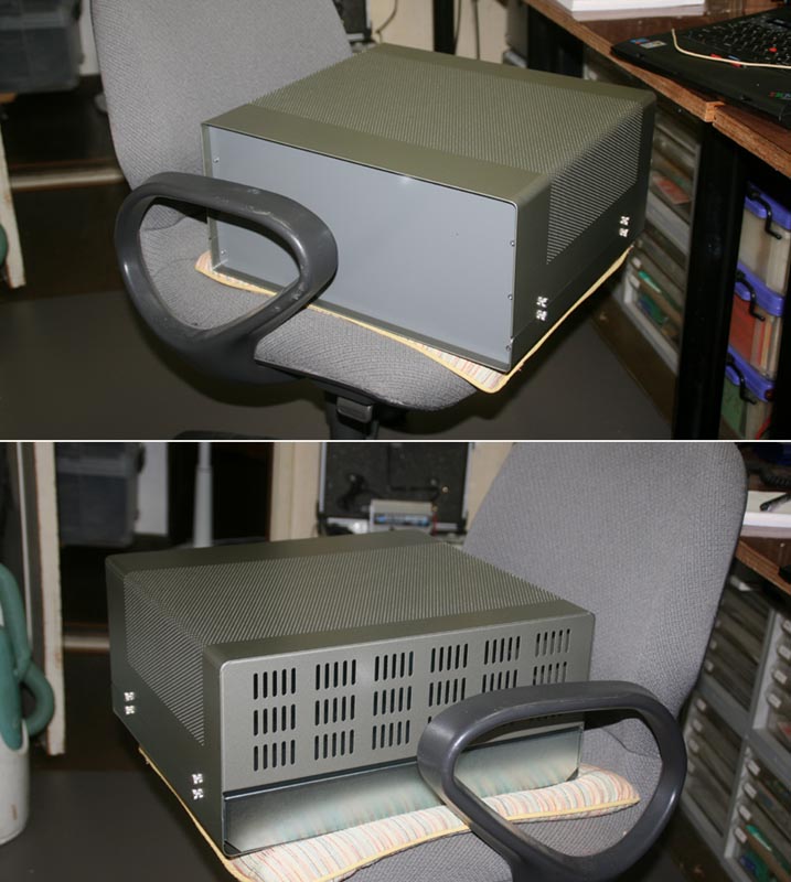
I recognized that there is not much choice for a cabinet which can accept a heavy power transformer, and has enough space for all band transceiver, with holes for heat radiating for vacum tubes.
This is IDEAL's UL-40, the same cabinet that I used forty years ago (!) to build the linear amplifire using four 4CX350s parallel. (I used one for power supply and one for amplifire, and used them piling up in two steps.)
It might be a problem that it cost expensive(US$180.00), but all what I should do is to appreciate them for their effort to keep manufacturing it and selling it still now. It is big and very reliable. As it is made of steel panel, processing is not very easy.
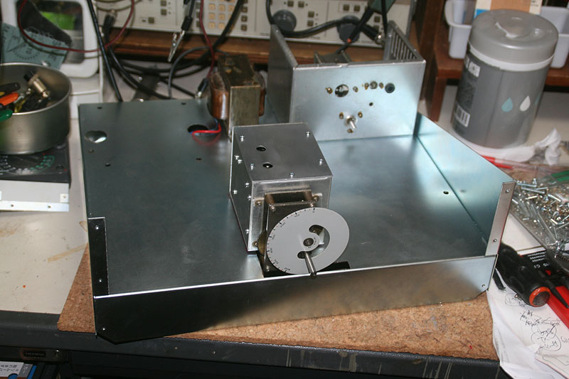
I took apart the VFO unit and gear dial mechanism to clean them up first. I started all the production with installing the VFO unit. (A very unique method of start, hi hi)
A steel panel is very hard, and I broke the hand nibbler which could not fight agaist the hardness of the panel. I rushed into nearby DIY shop to buy a blade for a zigsaw to continue the processing.
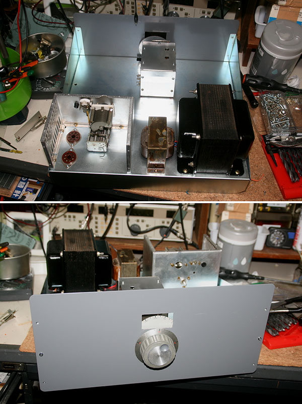
I installed a final shield box with socket for two 6146Bs, a power transformer, and a choke transformer, and opened a window in the front panel to install the dial mechanism. As the large mayor parts have been on now, it started to show its final atmosphere.
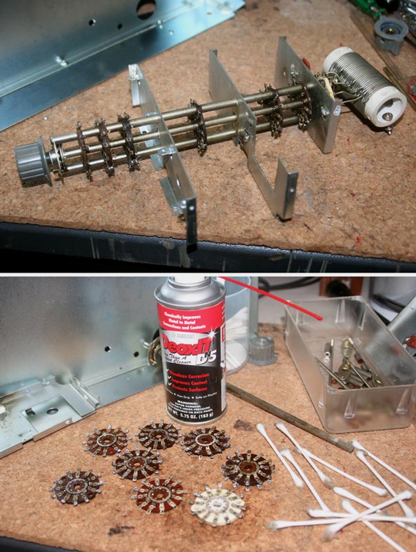
This is a band switch which was used for YAESU's SSB transmitter, FLDX-400 of 40 years ago. Oh, what a mess, so dirty... This old stuff may give me a lot of problems such as bad contact and electric leakage, no doubt about it! I took them apart completely, and clean all the parts one by one using amazing magic chemical, "Deoxit (D5)". I reassembled them into suitable structure for my transceiver, selecting wafers and adjusting positions.
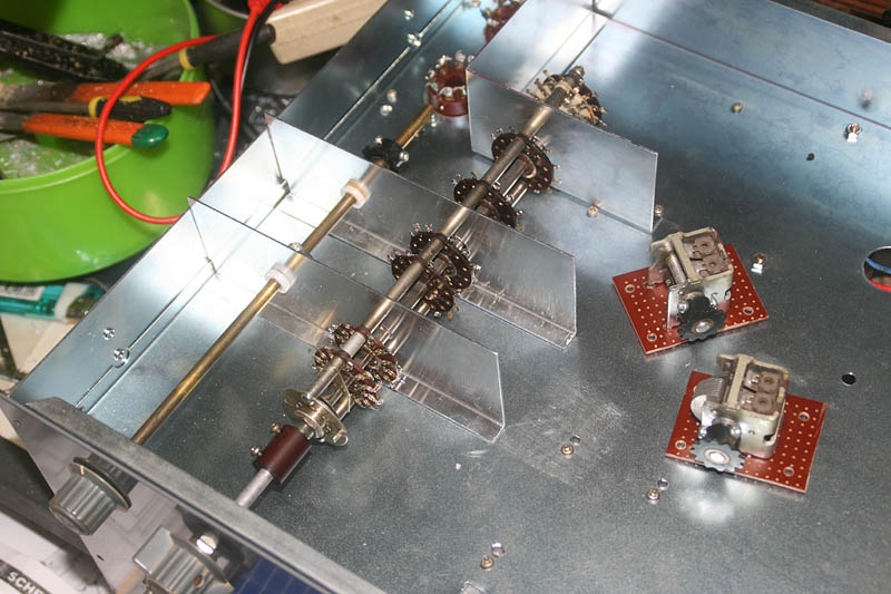
The band switch with shining contacts has been reassembled and completed by changing numbers of wafers and adjusting thier positions, sandwitching shield panel. A brazen bar adjacent is for turning two variable capacitors for the "Drive" tune togther by chains and sprocket wheels, and I have just finished the isolation processing for them. It is because the circuit requires to isolate thme from the ground, and I had to be troubled whole one night finding the method to realize it. I mounted the VC on the PCB, soldering the terminal of VC to the board, and then the PCB to be installed to the chasis with the spacers.
I firstly did the hardest part of the work, a metal processing around band switch and final tank circuit with tuning VCs. As I made reuse of tuning dial mechanism of TRIO TS-510, it already got a face of transceiver with just installing it to the cabinet. This dial mechanism used to have a very nice touch feeling as good as that of YAESU FLDX-400 (25KHz/turn model) and I loved it although I did not have TS-510 in my shack, but now I could get it after 40 yeras!
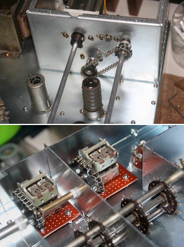
This is a tuning mechanism using chains and sprockets. (One for a LOAD VC above the chasis, and one for DRIVE VCs under the chasis.)
They move very smoothly.
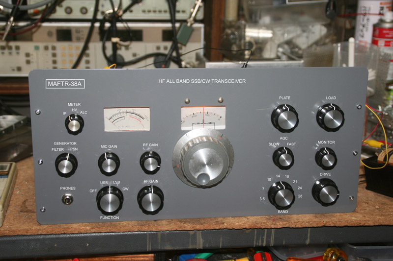
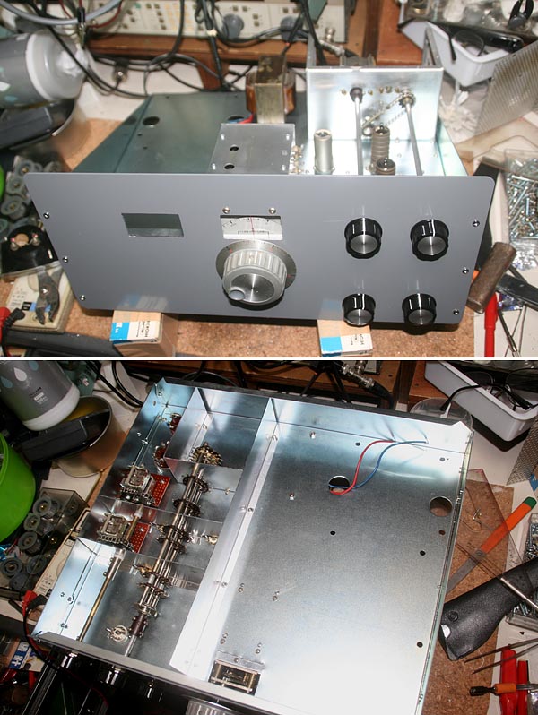
As the band switching mechanism which has the first priority in the physical design has been installed, I then determined all of the front panel design next. I installed the illumination lamps and wired temporarily to supply 6.3V to see how it looks llike to simulate the final outlook.
The actual lettering work has not been done to the front panel. I simply tried to add letters to the picture using an image edit software on the PC to see the finishing outlook.
There is no jack to plug in the microphone in the front panel. Well, it should be somewhere around where the headphones jack is located, however I happened to forget about it and drilled one hole right in the middle of the area for two jacks. So I decided to install the jack for microphone at the back of the cabinet. Yes, there is no reason to say it incoveniente just same as a key jack which is normaly placed at the back of the cabinet in most of the radios.
Cheking design of the front panel, using the parts from the TS-510 not only for the dial mechanism but also for the meter is really idealess without my originality.(hi hi)
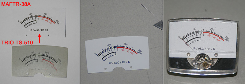
So I decided to make a new panel for the meter to replace it with the original one.
Especially, I had complains such as that HV (High voltage) is not needed, and S meter scale over S9 should be in red to match with my instant feelings. So I started the work witout any hesitation.
one.
(Left)
Remove the panel from the meter and capture its image with a scanner. Using an image editor software, modify the layout and appearance as wished.
This processing may need some experience for the technique and know-hows. After completing the desired panel, print the image to a white filem sheet (with the paste in its back). The picture shows the comparison with the original panel and the printed sheet.
(Middle)
Cut the film sheet fitting to the actual size and form of the panel, and stick it to the panel. Be careful no air bubble would be left between the panel and the sheet. Using a cutter knife, cut the film carefully if there left a part hanging out of the panel. Drill holes for the screw to mount using a bit of the drill.
(Right)
Set the panel back to the meter. A new meter is now completed.
This is what we always stare while in operation, so it is better to particular about.
Now, the chassis processing for tube sockets and IFTs. I don't think that it is too much to say that this determines success or failure oth this equipment.
The layout determine all the performance of an equipment using vacum tubes which input impedance and output impedance are very high and easy to cause induction, feed back and oscilation.
And once you decide and done prcessing to the chassis, you'll never beable to come back.
This is all that makes difficult for building tube equipments.
Checking the block diagram carefully, considering the signal flows, place sockets for tubes , Crystal Filters , and IFTs. Important large parts are these three.
Exact directions of each parts, and distances among parts is decided by checking the Circuit Diagram carefully, imaging wiring works. It is better to take a couple of days for re-checking all of these decisions, however I am not as patient as to do so. "I don't know! Let's go!" I do marking with a sign pen, and using a ruler, find a center of each parts and draw X marks. As soon as done so, it's better to drill holes on all Xs to avoid any mind changes, hi hi.
Now unable to get back! Oh, what a relaxing moment!... hi hi
What is the most dificult part of building a taransceiver would be a mechanism of band change, and building IFTs.
For IFTs, there is no method other than modify a commercial made IFT because a shield case is essential.
In this case, I was trying to use IFTs being used in TS-510, but there was a problem. Despite the all tube transceiver, the PCBs are used for TS-510 and therefore, all the IFTs can not be mounted to the metal chassis.
I troubled for a long time, but finally I decided to open a round hole for MT vacum tube for seven pins with a Chassis Punch, and install the IFT by bending leg pins 90 degrees to solder them to the back of the chassis. Well, thanks to the hard troublesome metal chassis because an aluminum chassis never accept soldering easily.
It is fixed to the chassis mechanically as well, and no problem for its intensity. Of course, it is necesarry to open all the IFTs to see inside wiring and note it in a circuit diagram. Otherwise, it is unable to decide the direction of installation. Two crystal filters are also installed safely.
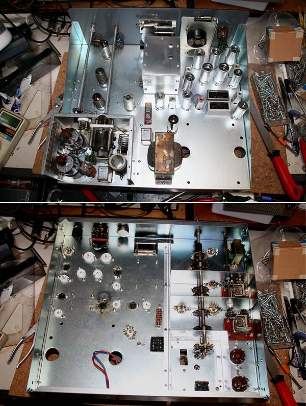
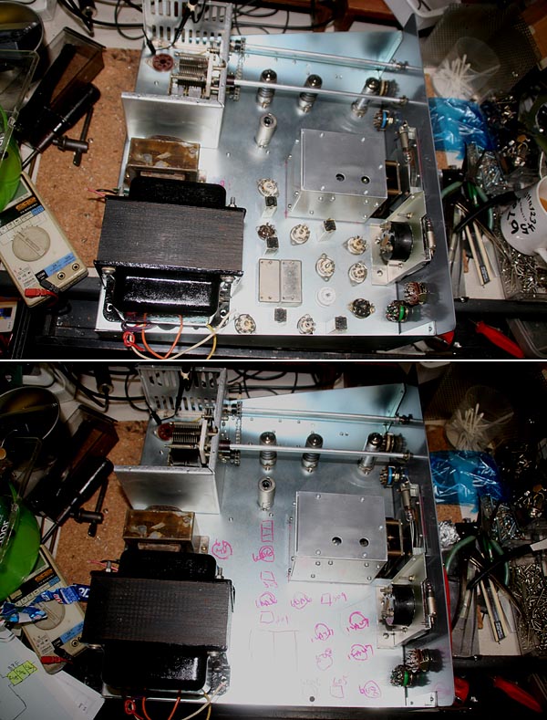
All the tube sockets have been installed and then the tubes as well. Together with IFTs, a band pass filter (Three IFTs for transistor mounted in series on a tip of PCB)and relays, which are major parts above the chassis, have been installed. Major parts in a shield box for the final tubes have been installed and the chassis processing thereing have been also finished.
The power transformer is too heavy to be installed at this stage. With the transformer installed, it is so hard to turn over or turn on side the chassis. It should be the very last work to install it. Even after the completion, for later maintenance, all the wiring should be done via patch board/terminals, so that the transformer will be easily removed.
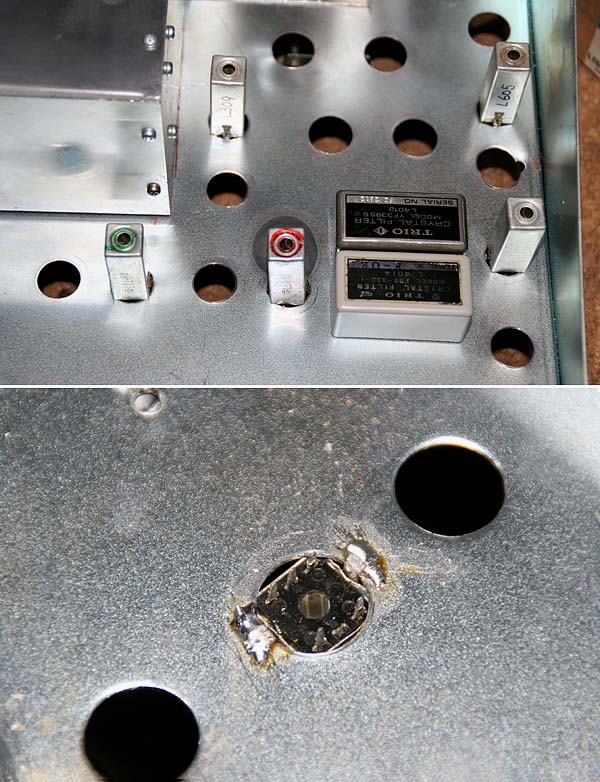
A part of the chassis which color is turned in black area around the IFT, is the evidence of my bungle.
As the chassis is made of a processed metal in its surface, a little filing is needed before soldering.
However, in the beggining, I didn't recognize it. With using a big solder arm of 100W, the solder never spread on the surface of the chassis, and then stupid I did not think deeply but heated the chassis with a gas burner, and then the plated metal on the sruface of the chassis melt in black and spread out! hi hi...
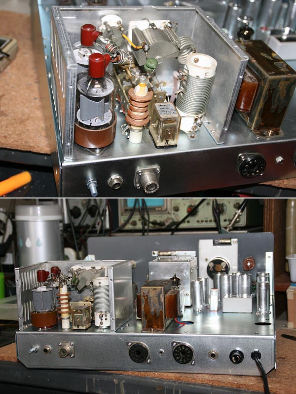
I finished most of wirings in the final shield box. Only the 14MHz band is wired now. It's easy to wire for other bands, but to start with, I dare try to complete as a monoband transceiver, so that possible problems should be reduced to the minimum for the success. I finised installing conectors to the back panel, as well.
Now, the appearance of this transceiver is completed exept lettering works. Finishing the metal work of the chassis and panels, Installing all the major parts to the chassis and panels, now the wiring is to be started.
(Whatever we build, the way to here is long and hard for the tube equipments. From here, we can enjoy the work relaxing, and blowing whistles.)
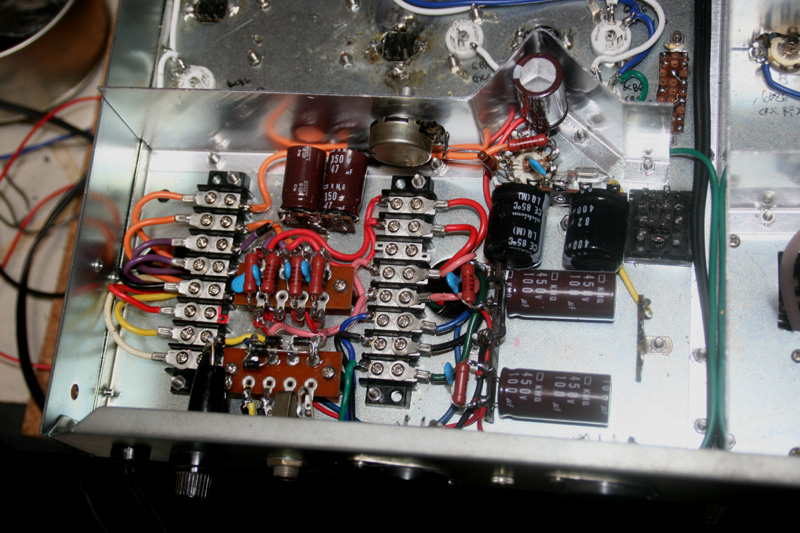
Working speed has been very slow as I had to wait for getting some parts, but anyhow, the power supply circuit is alomost done. The terminal blocks are used to relay all the 15 cables coming from the power transformer so that the serious maintenance should be easily done by removing the heavy power transformer.
== NOTICE ==
Now, I have to stop the work for a while. That is because I decided to challenge my last work in my life in Fiji, in the South Pacific Ocean. I have to stop the building this equipment right at the most interesting step. But I leave everything as it is in my workshop for a few years so that I will be very happy to be back home then.(Jan. 10, 2012)
 In case you hit this
page directly from a Search Engine, you can reach to all of the pages of MAFNET from Top Page
In case you hit this
page directly from a Search Engine, you can reach to all of the pages of MAFNET from Top Page