All tube 3.5-50MHz VFO
(MAFVF-350A)
[The last renewal of this page: November. 3, 2010]
This is a VFO which is used for AM/CW transmitter for 3.5MHz`50MHz (MAFTX-350A). I have to pay attention so that it provides sufficinet output power to dive all band including 50MHz stably.
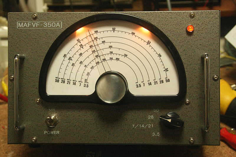
A dial is the most imporant face of VFO, adn I wanted to use MITSUMI's MD-5 which is the same one as I use for the relative receiver, but it is hard to find its junk even in the Yahoo Aunction as it is a product of 50 years ago. So instead, I got a junk of an old National'(Matsushita) measuring instrument at only JPY2,300(US$23.00) to reuse its very unique an old fashioned vernier dial with a large scale plate.
The cabinet is LEAD AS-3, which is a smaller model of AS-1. (The same as for the cristal convertor)
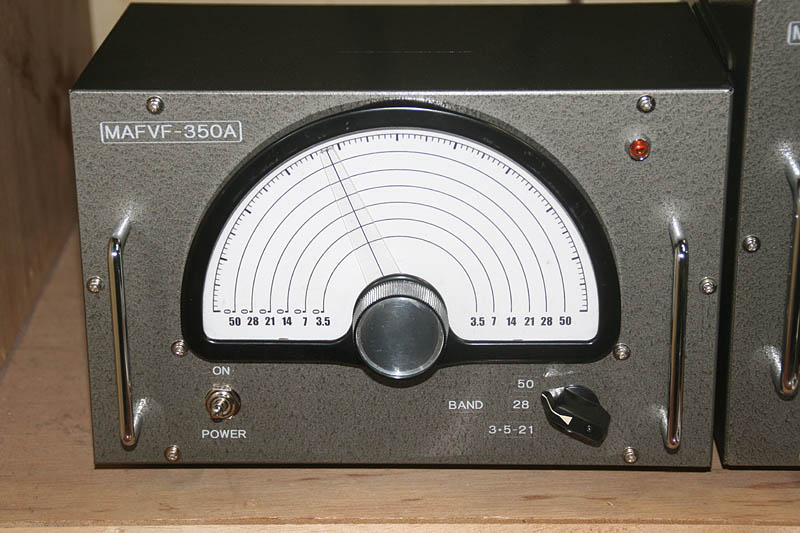
Following to the "External appearance before everything else" project, its appearance is completed although there's almost nothing inside.

This is the circuit diagram I completed as a first step.
As I intend to use junk parts of TRIO VFO-1 such as LC box, I refered to the original circuit of the VFO-1 in designing my VFO. As I don't like to stop the oscilation during the reception, I installed a relay to short the output to the ground, keeping the oscilator tube on all the way, although the B+ is cut for other tubes during the reception. If later, I find the problem with this, such as a leaked carrier, I would resolve the problem adding a small capacitor to the osicilation circuit to alternate the frequency.
This diagram is only for the time of starting work, and it will be amended lots of changes as the actual process goes by. (The final diagram will be shown after the completion.)
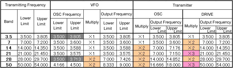
This table shows the frequency structure of transmitter together with VFO.
The oscilated frequency it self of the VFO is based on 3.5MHz for all bands except 50MHz. Among those bands which original oscilation frequency is 3.5MHz, the 3.5MHz band and the 28MHz band require wider range than rest of the bands. To spread out wide on a scale plate, it is sesigned that those two bands are separated in one group by switching the band switch, adding extra VC in parallel to get more variable capacity.
So, let's see what's going on!

The dial is the most important parts what you see during the operation, and I wanted to use MITSUMI's MD-5, which is the same one I use for the relative receiver, but as I could not find the way to find one in a short time, I got this junk of measuring instrument. I removed the dial mechanism to check, and found it a very professional structure, and maybe better than MD-5. Of course, it is nice for my VFO.
I redrew the scale plate with the same method I used for the receiver. The problem was to draw the concentric circles, and I finally made it usigng Microsoft Power Point, but I needed another screen capture software to get it as a graphic file, because the Power Point could not perform well in saving as a JPEG file in its resolution. I then edited the file using Adobe Photoshop to do some composition work. After all, I spent a whole one night only for redrawing the scale panel.
As it's impossible to determine the accurate division of the scale at this point, I left the division of protractor at the most outer line so that I could check the actual frequency and the angle of the dial when I complete this VFO. I will then redraw the sacale plate again.
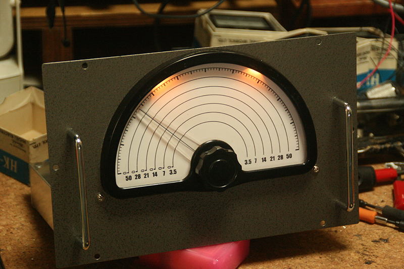
There was no space for the mini-bulbs for the illumination, but I drilled small holes at inside the frame to get the bulbs in.
A nice feeling with the illuminations, indeed. A nice toutch the vernier dial as well.
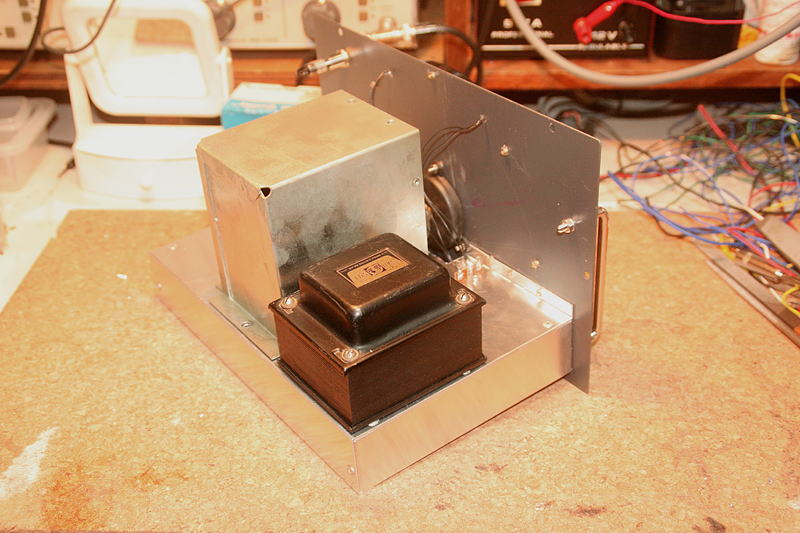
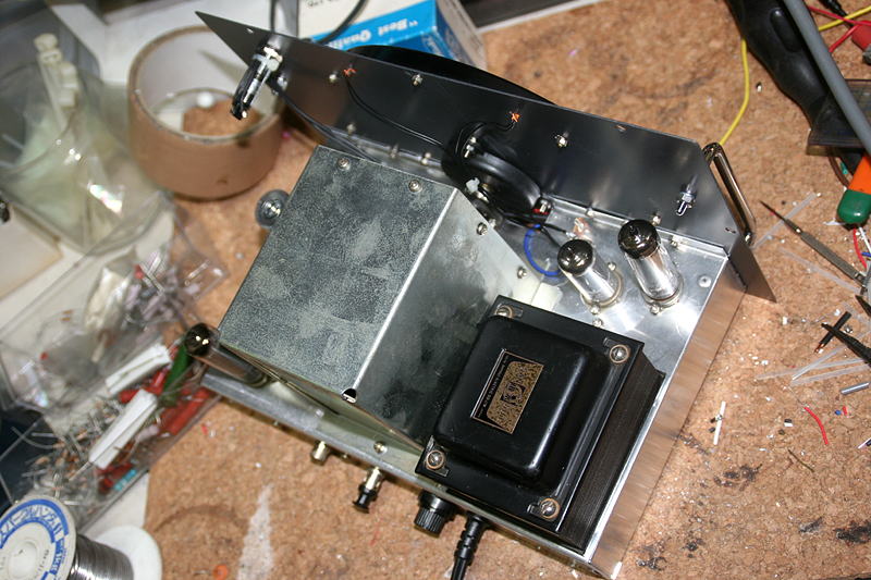
I mounted a LC box and a power transformer. As the transformer that I firstly planed to use was too small and there was a possibility to be heat up, so I exchanged it to the new one. So I needed to enlarge the hole to fit the new one, and I even had to cut a bottom part of the LC box for that.
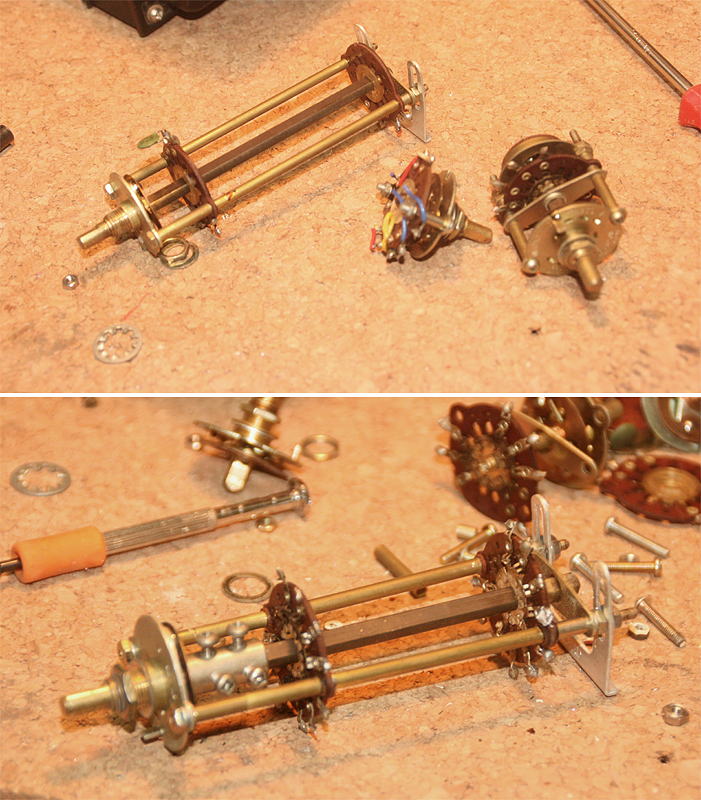
The first problem was a rotary switch. One I removed from the VFO-1 has 2 circuits and 3 contacts (The above picture), but I needed 3 circuits and 4 contacts! This was my first experience, but I decided to modify the rotary switch.
I took apart sevral rotary switches that I had, and selected usable contacts plates. I took away only a long shaft and long screws and pipes from the one for the VFO-1, and assembled them adjusting length of each parts to be a rotary switch of 3 circuits and 4 contacts. (The bottom picture)
** The front panel that I previously completed shows the rotary switch has 3 contacts, but after examing the circuit, I recognized that I need one more contact and circuit if I want to switch the L/C in the output resonance circuit together with the band change. (Four bands like 3.5, 7/14/21, 28, 50)
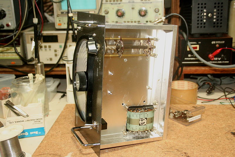
The rotary switch was set safely. You can see the horrible work to cut the chassis for the transformer. It's too sad to see. I will do a finishing work later.
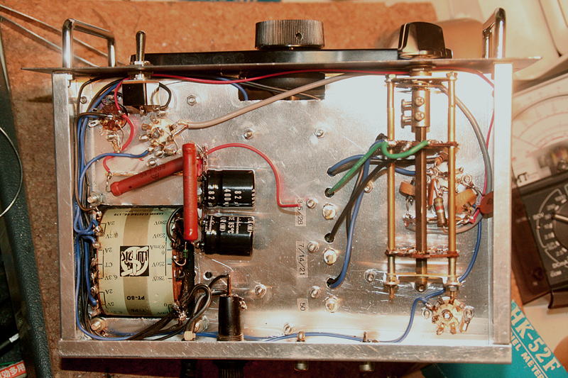
I worked and completed inside of LC Box, whic is the most important part of VFO, first.
I reused all the parts from the VFO-1 for here. I worked carefully taking a time as this is a very important part.
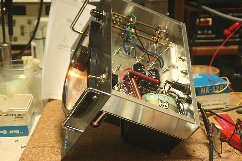
Under the chassis, I started to work from power suplly circuit. After this wiring, I spent a mysterious and wonderful time watching illuminations of the dial, pilot lamp (Neon lamp), and the violet light of the constant-voltage discharge tube, hi hi.
The violet light from the constant-voltage discharge tube is really something always, isn't it?
That is a moment that I feel the tube equipments are so nice.
Hey, Mr/Ms Solidstate Digital Equipments, if you're making your blood boil, let me show your beautiful violet light!
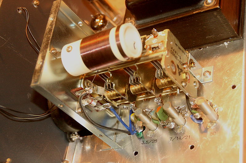
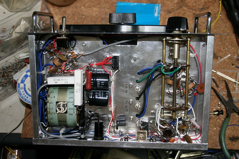
Wiring around 6BA6 is finished. Right below(above) the rotary switch. The space is extremely limited and the 3D work is required.
At this point, let the power on to confirm the oscilation. I was doing a work monitoring 80m with YAESU FT-817 on the side, and as I turned the dial of VFO, a big beat sound came out from the FT-817!
The carrier is very clean and very smooth beat. There is no QRH since right after the switch on! Well, of course, this is because the cabinet is opened, and there is no rise of the temperature inside the LC box, but it is just like the switching on the 100KHz marker of the SSB transceiver.
The beat varies really smooth as I give a turn to the dial, which reacts very comfortablly. It is so early to say, but at this point, I felt a strong self-confidence that I would be able to complete all the transmision system perfectly with an actual practicality.
All the wirings have been finished. I spent a hard time around the sockets of the tubes beacuse of the extremely limited clear space. Using a special technique of 3D work, I anyhow finished. the shallow chassis of this cabinet was another problem for easy wirings. It is a weak point of the "External appearance before everything else" disign, hi hi.
This shows the above the chassis. Now is a step for adjustment.
I spent many hours and a hard time at the part of resonance circuit of the final tube, but after the adjustment work for whole one day, I could get the stable output for all bands,
I went straight to connect to the transmitter(MAF-TX-350A). I was worrying about if the output power of the VFO is much enough to drive the transmitter for each band or not, but I could confirm it work oproerly for all band.
I tried to connect a 8V small bulb to the output for low impedance, and the bulb shined at its maximum brightness. I checked the power with a dummy load and a power meter, and it was up to 1.8W! It is a transmitter with a 6AQ5 for final!, hi hi
When I first checked the brightness of the bulb, only the 7MHz output(for 28MHz band) and 8MHz output(for 50MHz band) turned on the bulb just slightly, and I was worrying about so much, but actual connection and operation proved that there is no problem at all, showing the same transmitting output power of the transmitter as a crystal.
What was much harder was a calibrationa and a production of the dial scale. Using a frequency counter, I marked with a pen at evry 10 to 100KHz for all bands, Then I measured the angle of protractor of every spot to give a rotation to the Photoshop with which I redrew the scale putting major divisions. All the work required me 12 hours of work.
I printed the scalet to the pro-photo paper in the acutal size, and get it laminated, cut it in the same shape as an original aluminum scale panel, and replaced with it.
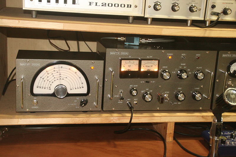
This is the transmitter sytem being completed. Connecting a vertical whip antenna (8.3m long) and ICOM's ATU AH-4, I am enjoying with giving it a try to get tuning on all bands. Now, I'wishing strongly to get the receiver completed as soon as possible.
I am looking foward to having QSOs actually with this rig. It maybe hard to find a counterparty that could work AM, but as long as using CW, nothing is a problem. I am already exciting with it.
This is the final circuit diagram. If you need detailed image, please download a PDF file
 In case you hit this
page directly from a Search Engine, you can reach to all of the pages of MAFNET from Top Page
In case you hit this
page directly from a Search Engine, you can reach to all of the pages of MAFNET from Top Page