All tube 3.5-50MHz AM/CW Transmitter
(MAFTX-350A)

[The last renewal of this page: November. 3, 2010]
This is a 10W transmitter of AM/CW for 3.5MHz to 50MHz. It's really orthodox with out any special features.
| TX Frequency |
3.5/7/14/21/28/50MHz |
| TX Mode |
AM/CW |
| TX Power |
10W |
| Final Tube |
6146 |
| Modulation |
6BQ5 Push-pull/Plate -Screen Grid Modulation |
I was lucky to have three sets of junk of TRIO TX-88D, so I decided to reuse the parts for RF circuit.
For the cabinet, I chose a nostalgic LEAD AS-1 without any hesitaition.
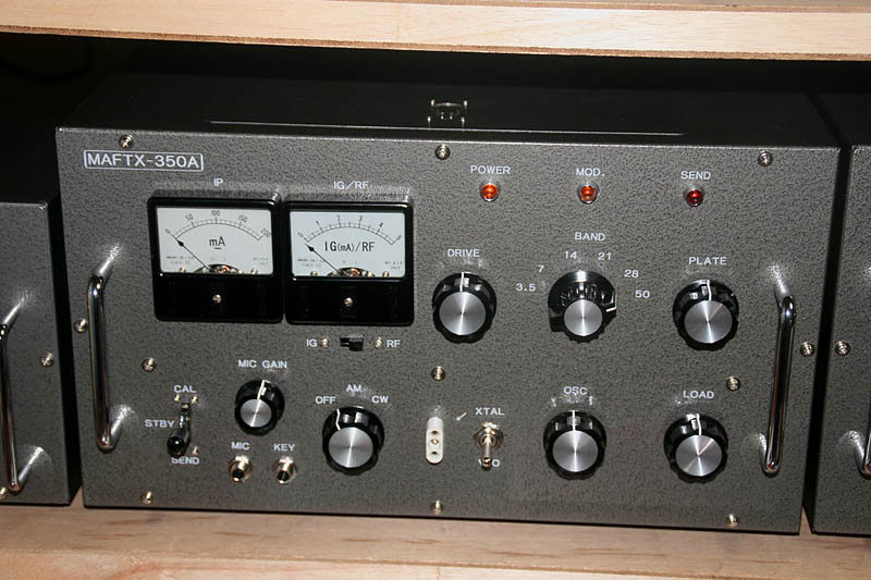
Following to the "External appearance before everything else" project, its appearance is completed although there's almost nothing inside.
It has a feeling to put out a powerfull signal!
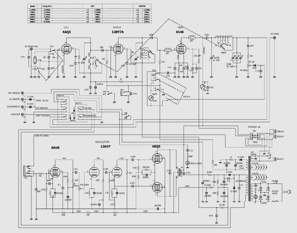
Finishing the circuit diagram, then. The circuit for TRIO TX-88D is basically imported because of usage of its junk parts. As a matter of fact, as an AM transmitter which widely covers from 3.5MHz to 50MHz, TX-88D certainly has a well designed circuit. For 3.5MHz and 50MHz, original oscilacion requencies and multiply numbers are different, and considering the diffrence of the signal levels, all band transmitter seems really difficult.
TX-88D is well designed in this sense, including TRIO VFO-1 which is a VFO being matched to it, which has an enough output power (It's a transmitter having 2.5W output power at 3.5MHz!) to let TX-88D to work properly for all bands. There is no reason not to learn from them.
For the modulator, I used a simple P-K division which does not require a phase invert transformer.
I used two meters, because switching one meter for multi-purpose with switch is not friendly. The plate current is required to be monitored always, while the grid current is only for the adjustment. RF meter is better to be monitored always. So, I decided to use one meter only for IP, and the other one for IG and RF being swithed.(Switched to IG only for it is necesarry.)
I wanted to use a fifty years old black meter, but what I got was a 5mA meter, and unable to attach a shunt resistor which enable meter to be grounded all the time. So, I had to use a relay to switch the meter circuit.
This diagram is only for the time of starting work, and it will be amended lots of changes as the actual process goes by. (The final diagram will be shown after the completion.)
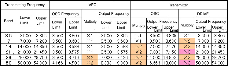
This shows the frecuency structure of this transmitter including the VFO.
So, let's see what's going on!
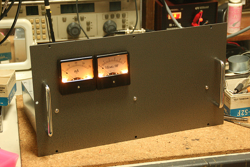
I started from making holes for meters. This is a fundmental rule for AS-1, which has a thick metal panel!? In my student days, I used to fight against the metal panel with only a hand drill, a file, and a nipper taking a whole day to make two holes for meter, making a lot of blood blisters, whichis now a good memory.
The right meter was for 100mA, and without a shunt resistor inside, it seemed to be a 5mA meter. So I redrew divison panel with graphic software after scanning it with a scanner. I print it to the print paper with a seal in its back, and stick it to the meter panel.
Illuminations are essential. I installed two mini-bulbs.
You see my rough work for meter holes! Well, if I try to finish it perfect, all the families would have to endure horrible noise of file work due to the resonance of the panel....so It's Okay, leave there! It is completely invisible and nothing is related to the efficency.
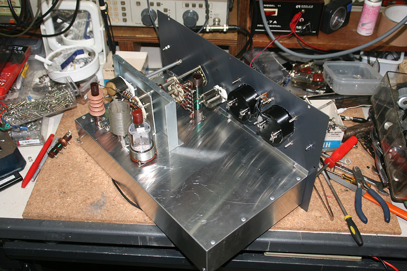
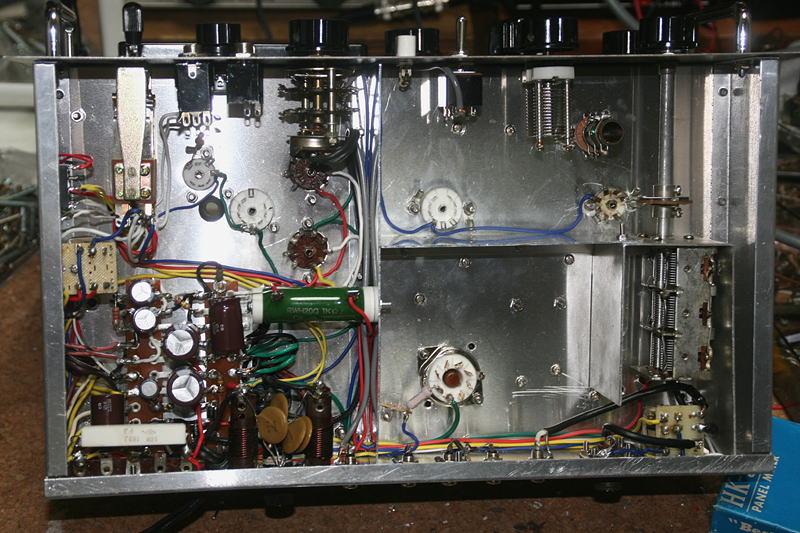
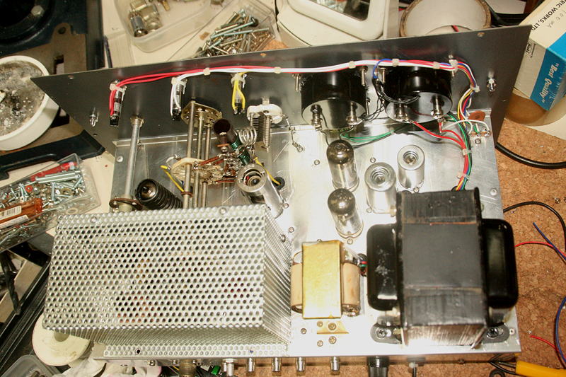
Useful RF parts of junk of TRIO TX-88D helped me. This chassis has limited depth, and the final tank circuit has very small space.
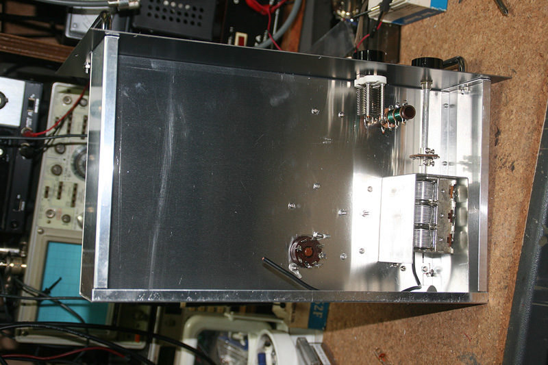
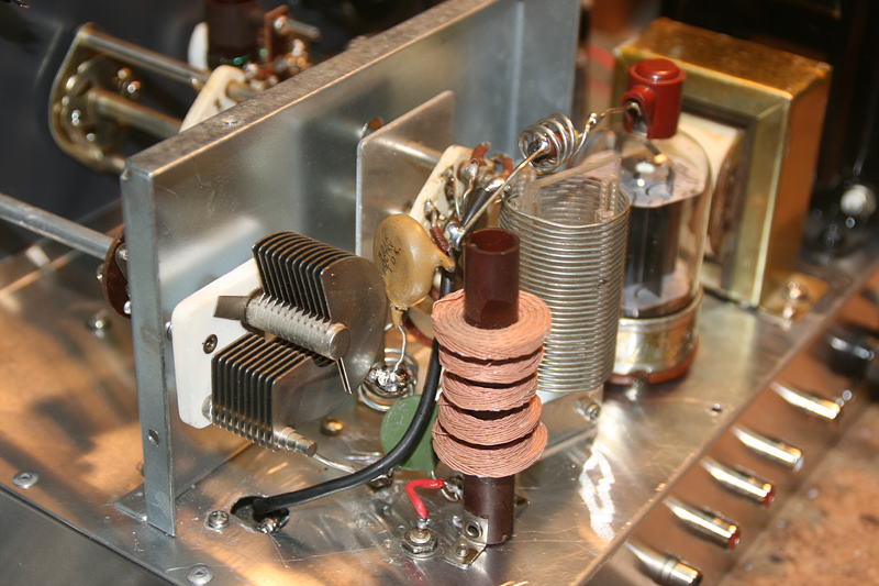
In the back of the chassis, the OSC coil and VC for LOAD are installed.
Instllation of parts to above the chassis is almost finished.
The first plan was to place in a good order in the straight line from the 1st stage of modulator to the phase reverse, however, the Siemens key which was planed to install at the right bottom of the front panel has been moved to the left bottom due to the placement of RF circuit, and as a result there left insufficiente space for modulator circuit. (Siemens key occupeis a large space in the chassis!) I recognized this when I tried to drill holes for tubes in modulator circuit. After all, I had to place the circuit in a limited space aligning in a slant line. It seems very hard to install small parts aroud tube sockets, but I may anyhow achieve it.
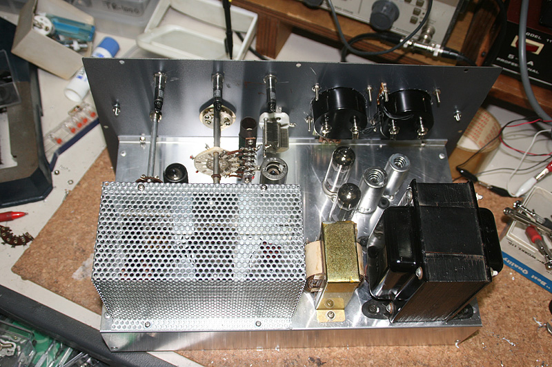
Major parts such as shield plates, relays, terminal tips for transformer and connectors at the rear of the chassis have been installed. Now the wiring is to be started.
I firstly completed the most tiresome seection, power supply and control system. At this point, check the voltage of junk transformer, and if the illuminations and relays work properly or not.
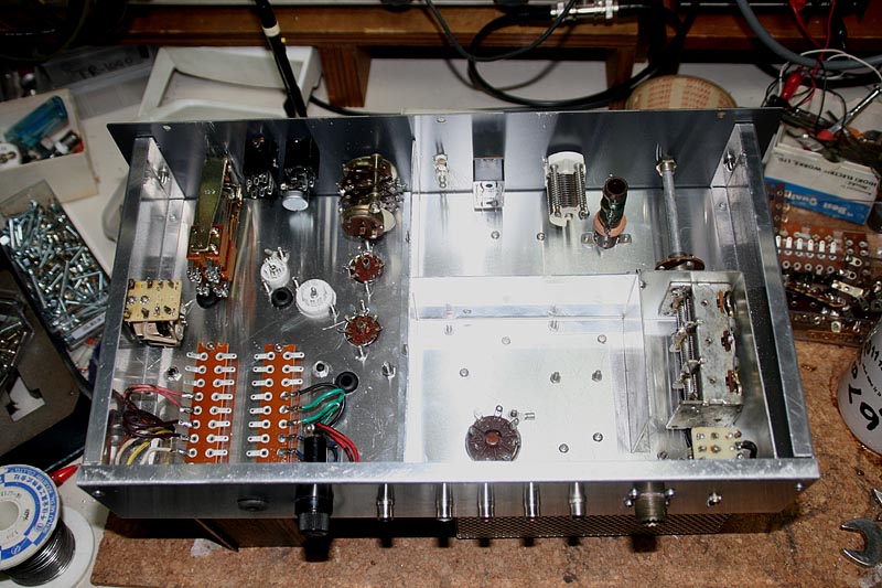
The next tiresome section is AF amplifire. I completed this, together with detailed part of the control system.
For convenience of wiring a circuit of meter switching, I completed the area aroudn socket of the final tube near by.
I found that I missed a red neon lamp for transmission indicator in the circuit diagram, and I recognized that I need one more contact of the relay to switch it on and off.
There was no contact remained, so I had to install a small DC12V relay just for this purpose. (On the chassiss's wall at the left of the Siemens key) I have an obsession to the neon lamp for this series of rig, anyway.
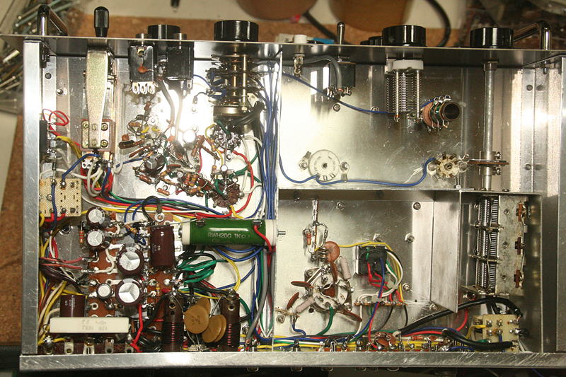
Weel it's turn to work RF circuit which is the most interesting part. As this transmitter includes 50MHz, all the wiring should be extremly short.
Everthing should be tight tp together in the final tube circuit.
At the back of the chassis, wiring was completed in shortly after it started. RF circuit is really simple and does not need much time as long as you have completed making coils.
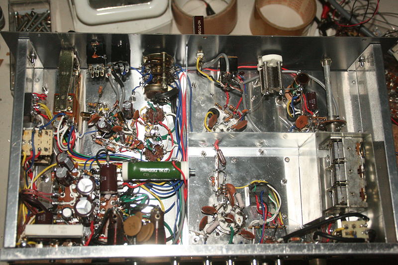
It's completed! Only the adjustment is left. I'm sure that it never works at its first switch on....hi hi.
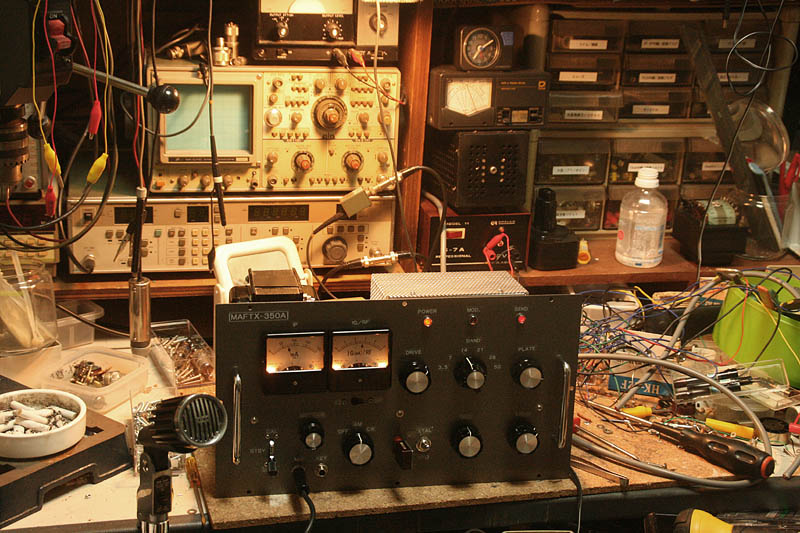
There was no mistake in wiring. However, there was no by-pass capacitor at the powersupply side of RFC of the plate circuit of the final tube in the circuit diagram, and no resonace was detected with a grid dip meter. Other than that, there was a stupid trouble that a scrap of solder was sticked between final tank coil..hi hi. After switching on the power, RF power comes out at once, anyway.
It's operation seems to be very stable, and there was no movement at all in IG meter and RF meter even though I turn all the tuning nobs after removing a crystal from the socket.
I tried to monitor with YAESU FT-817 which is set on the side, I found the carrier quality is excellent for this tyue of AM transmitter. The level of hums is low enough to forget. I intended to connect a microphone to try AM modulation, and found a clear and an excellent modulation! As long as I monitor, the quality of the modulation is super. Moreover, an excellent S/N! It is far different from the all tube 3.5/7MHz portable AM/CW transceiver (MAFTR-37A) which I built a couple of months ago. I kept the rule of one point ground in mic amplifire circuit, and the rule for wiring with shielded wire (ground point). More over, the trourble that I lost the space for modulation circuit due to the change of the place to mount a Siemens key helped the wiring in a short distance as a result. All of these seem to made a good total effect.
Well, I measured output power for each band.
| BAND |
OUTPUT |
| 3.5MHz |
14W |
| 7MHz |
13W |
| 14MHz |
12.5W |
| 21MHz |
12W |
| 28MHz |
10W |
| 50MHz |
6.5W |
|
Plate Voltage |
Plate Current |
Input Power |
| Min. at resonance |
302V |
85mA |
25.7W |
| Max. at resonance |
328V |
70mA |
23.0W |
At all the HF bands the output power satisfies 10W, but at 50MHz it comes down due to the efficiency. Though I paied much care about shortning the wiring aroud the band swithes, for an all band transmitter I may have to accept this result.
Only the detailed adjustment and fixings are left now.
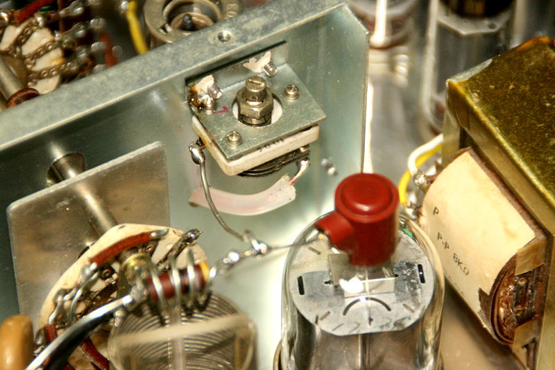
I found there happened a unclear modulation while I was tuning carefully on monitoring AM modulation with the headphones, so I installed neutralization circuit and neutalized the final tube. I had a junk of VC for this purpose which I had removed form YAESU FLDX-400, so I used it.
The operation is stabilized, but the power was reduced to about 5W (Only for 50MHz). The 6146 which I am using for this transmitter is a very old one, so it may be increased to near 10W even for 50MHz if I exchange it into new one.
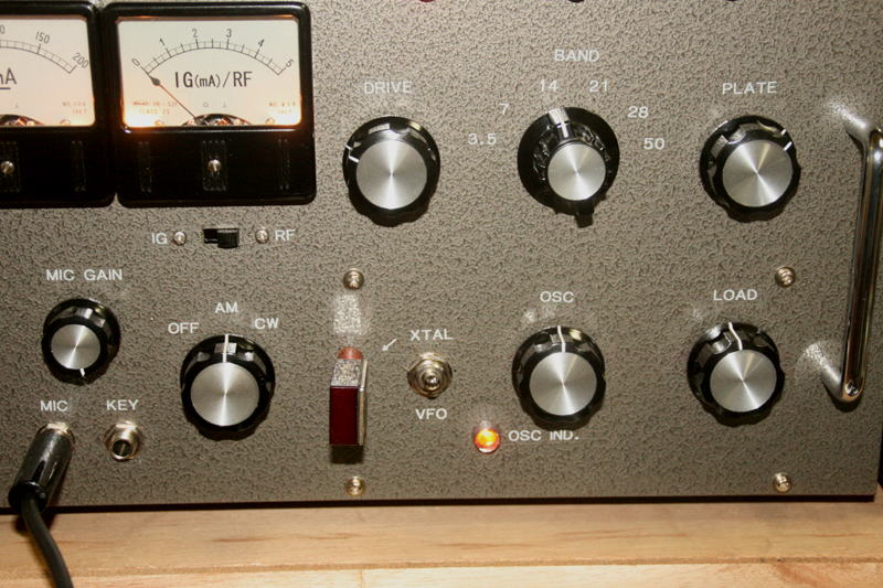
After actual operations, I recognized it is hard to find a tuning point of OSC where the IG starts to flow. So I installed a neon lamp as a indicator of oscilation. At the bands above 14MHz, OSC stage is resonanced so that the neo lamp will be turned on at its oscilation, and this is very useuful especially tuning at the new band after the QSY from another band.
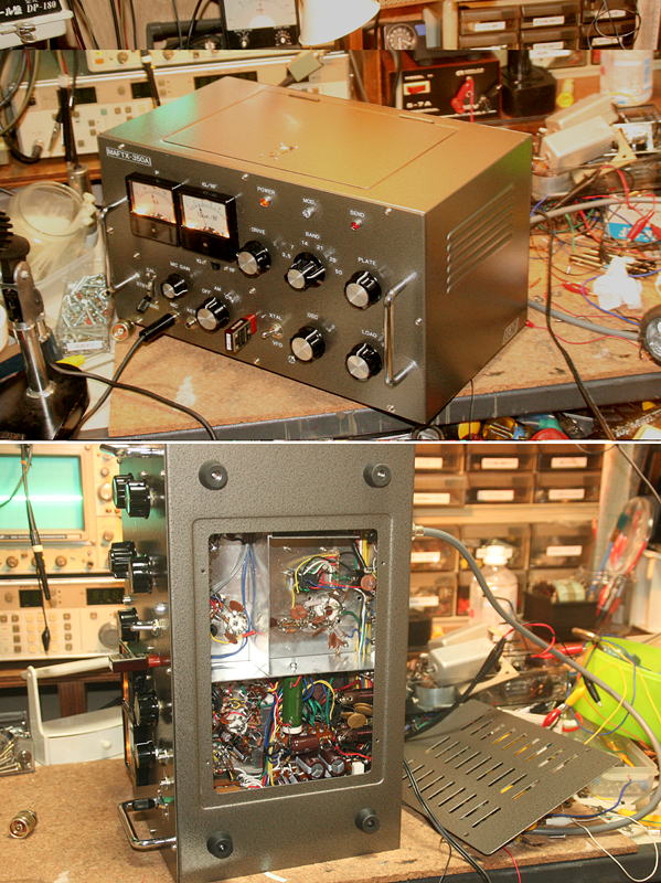
The cabinet LEAD AS-1 is really super! The top panel has a hinge to be opend for the maintenace (could be for cooling?!), and the bottom panel is easily removed bu unscrewing a couple of screws to enable us to adjust and dimple fixing or midifications.
The sidpanels and a rear panel have ventilation louvers, and there is no doubt that nothing is existed better cabinet for the tube equipment than this. It is obvious so considering the fact that they have been producting it for more than 50 years! It has reached a high degree of perfection.
Only the problem is a thick metal front panel! (I'd never drill a hole for meter again!) It may be better exchanging the front panel to aluminum one.
This is th final circuit diagram. If you need detailed image, please download a PDF file
 In case you hit this
page directly from a Search Engine, you can reach to all of the pages of MAFNET from Top Page
In case you hit this
page directly from a Search Engine, you can reach to all of the pages of MAFNET from Top Page