All tube 7-50MHz Crystal Convertor
(MAFXC-750A)

[The last renewal of this page: November 8, 2010]
This is a crystal convertor covering 7MHz to 50MHz to to be connected to the receiver for 3.5MHz to 4.0MHz (MAFRX-35A).
Many articles in the past Japanese CQ magazines regarding homebrew crystal convertors had a style to separate 50MHz from HF bands to be independent, but I will do it in the same circuit, the HF bands and 50MHz together switching it with a rotary switch.
If I start every thing from the parts, it will be a tough work, so I used a coil pack being used in a junk of TRIO's pre-convertor, SM-5D. As the 3.5MHz section is not encesarry (3.5MHz is received by the receiver directly as a single super heterodyne), I will modify the section for 50MHz. This is my idea.
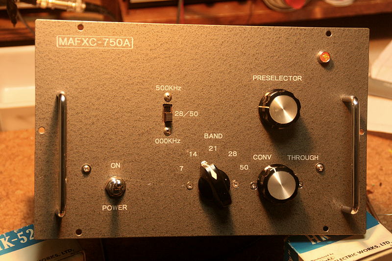
As I wanted to use LEAD AS-3 cabinet, the coil pack is large enough to restrict the disposition, and there was very limited choice for the disposition of the nobs in the front panel.
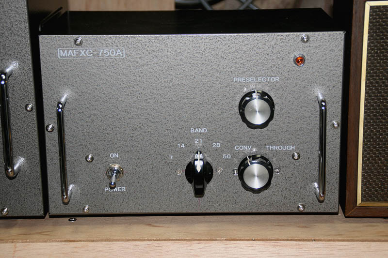
Following to the "External appearance before everything else" project, its appearance is completed although there's almost nothing inside.
This is the circuit diagram being comleted. As I use a coilpack of the TRIO SM-5D, the circuit is much based on the one for SM-5D.
This diagram is only for the time of starting work, and it will be amended lots of changes as the actual process goes by. (The final diagram will be shown after the completion.)
So, let's see what's going on!
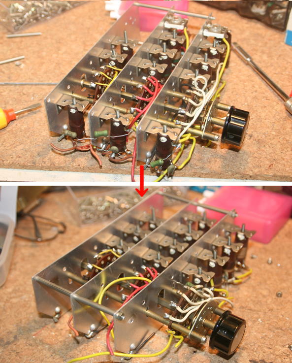
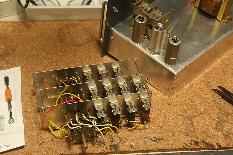
I started with modfication of the coil pack which I removed from a junk of TRIO's Pre-Convertor, SM-5D.
The coil with a trimmer on top in the above picture is for 3.5MHz. So I removed that coil, and shiht the position of all the coils toward the vacant space. To realize this shifting, I needed to take the rotary switch apart so the all of the coil pack as well.
At the most near side (Left of the rotary switch), where 28MHz coil was located is now vacant, so I will make a coil for 50MHz and mount it there later. (To shorten the lead for 50MHz minimum. this shift is required)
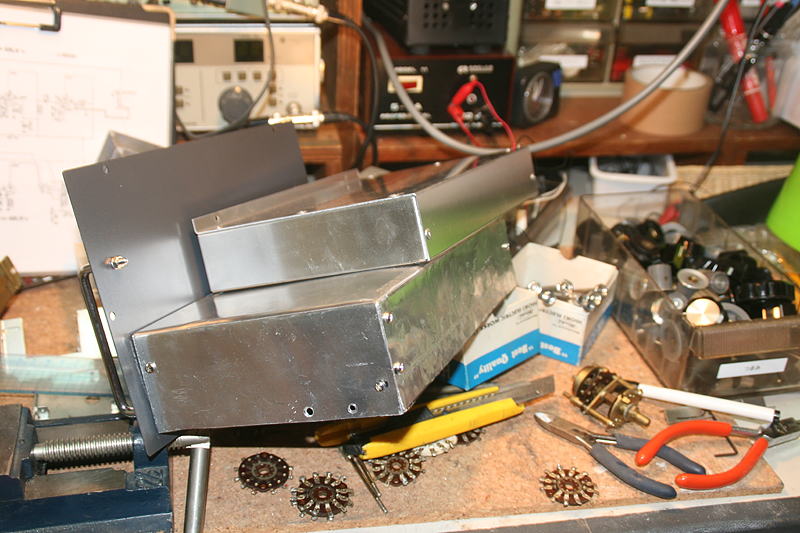
The cabinet LEAD AS-3 has a really shallow chassis, and the coil pack is not fit into the chassis. So I had to make a chassis by doing a sheet metal processing to another chassis that I had, and replaced with the original one. It's certainly a rough work, and you see the horrible finishing as in the picture, although it got a sufficient strength.
(A chassis placed on top is an original chassis of AS-3)
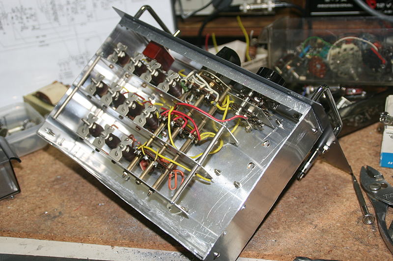
The coil pack is mounted to a chassis which does not seem too bad? from the reverse. However, the clear space for the tubes (right side) is very small which force me a hard work from now.
Three tubes have been mounted in a limited space. Almost no space is left for the wiring.
At this point, I temporarily removed the coil pack. When I moved all the coils to get space for the coils of 50MHz at 28MHz coils had been mounted, all the wirings within a coil pack were cut in pieces, so I have to rewire them in a good order.
Rewired all. It seemed to be a tiresome work, but actually, it was a comfortable work.
Coils for 50MHz have not been prepared yet.
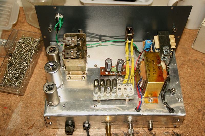
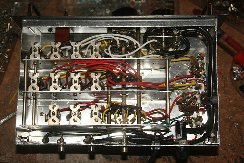
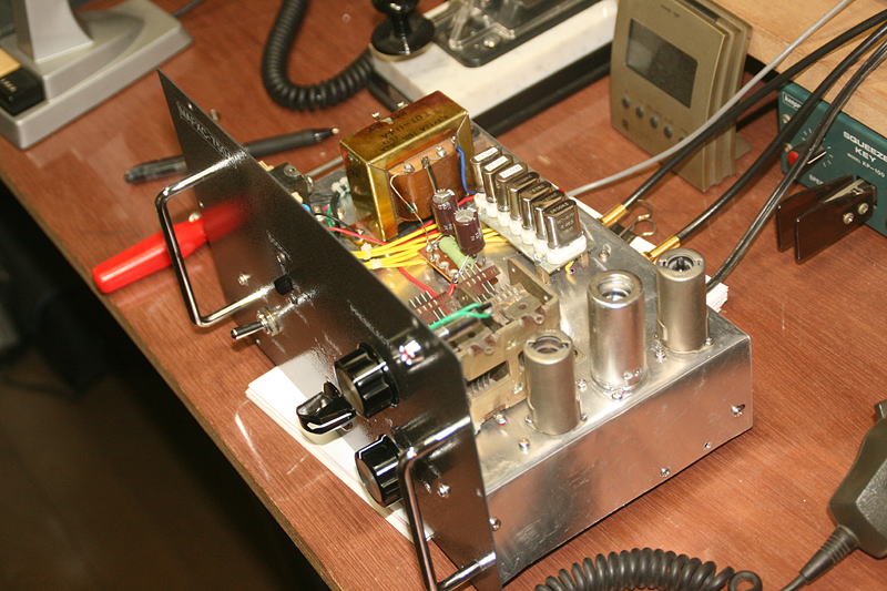
I finished the wirings above the chassis. Other than a power supply, I mounted crystals for local oscilator for each band. A base plate for the socket of the crystal is a junk parts from the old TRIO's TR-1000 (Solid state 1W AM tranceiver for 50MHz in 1960's), and if you have TR-1000, you'll notice it at once. It's for five crystals, but I modified to add one more socket in both side of the plate, where the hole for the screw for mounting is opened, so that it could hold seven crystals.
The receiver in this series of equipments covers 500KHz from 3.5 to 4.0MHz. So, for 28MHz and 50MHz two set of crystales are to be prepared, to cover 28.000 to 29.000, and 50.000 to 51.000, respectively.
I added one slide switch to select crystals (H/L) for those two bands in the front panel. Three crystals are still under special order.
For the stand-by method, I kept examining till all the way, but after all, I judged that there is nothing good if I extend a wire from the cathode for stand-by even it is bypass to the ground by a capacitor, and gave it my mindo to do so.
The final idea was to use 12V relay to cut the +B line, but there is no power supply for 12V. I was troubled for a while, but after all, I tried to take apart a junk AC adaptor for DC12V/500mA, to find a small transformer and rectification circuit which looked just nice for this case. I mount them above the chassis, and there you're.
A slide switch being added to the front panel to switch crystals for Lower band (28.0 to 28.5MHz, 50.0 to 50.5MHz) and Higher band (28.5 to 29.0MHz, 50.5 to 51.0MHz).
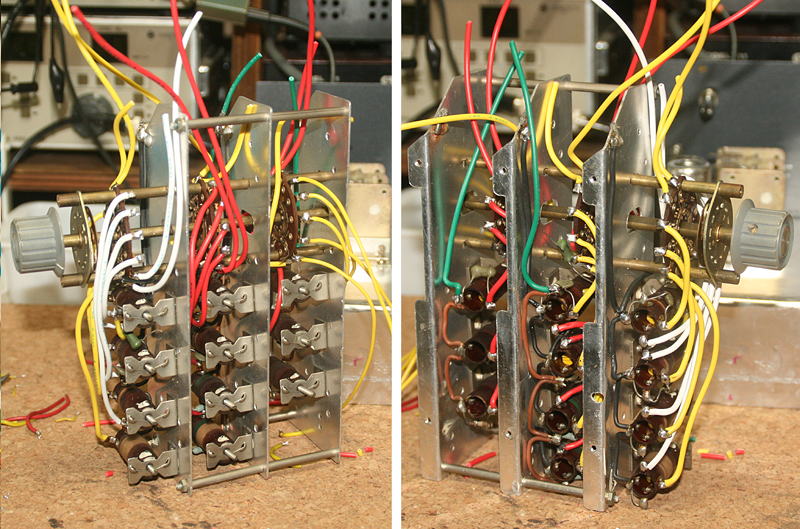
Wirings in the back of the chassis have been completed, except coils for 50MHz. (A clear space at the right of the rotary switch.)
I was worrying about the space around three tubes, but as I had studied and learned a lot with such a problem in building a transmitter and a receiver so far (hi hi), that was not much problem at all.
Now, I have to make coils for 50MHz.
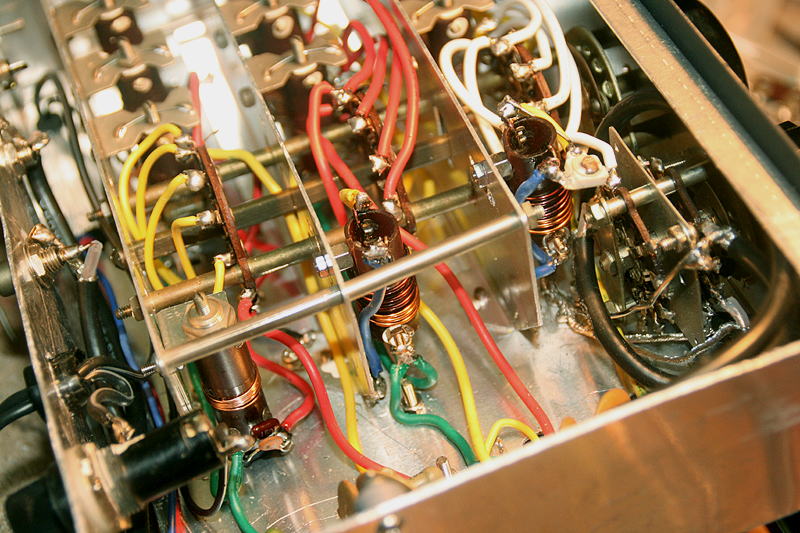
Taking a whole night, I made coils for 50MHz. They are in the row of the most near side. From the left to the right, they are OSC coil, RF coil, and Antenna coil.
For the OSC coil, an OSC coil being left from the set of receiving coils which used for the receiver (MAFRX-35A) had the same size with a core, so I decided to use it. I rewinded a coil again.
Through a few times cut and try, I could get a suitable turns to cover the frequencies of two crystals.
I made an antenna coil and RF coil using bobins being used for the AC line filters in TRIO's TX-88D (All tube all band AM/10W transmitter in 1960's).
These coils are affected very much by wirings to the band switch, and only way to make them was to repeat cut and try. I did it for four times, and finally I go a suitable turns (4 turns).
After mounting them, I checked the resonance frequency with a grid dip meter, and found a little bit difference of frequency due to the difference of the wirings' length, so I added a small ceramic trimmer to the antenna coil to set them at the same frequency.
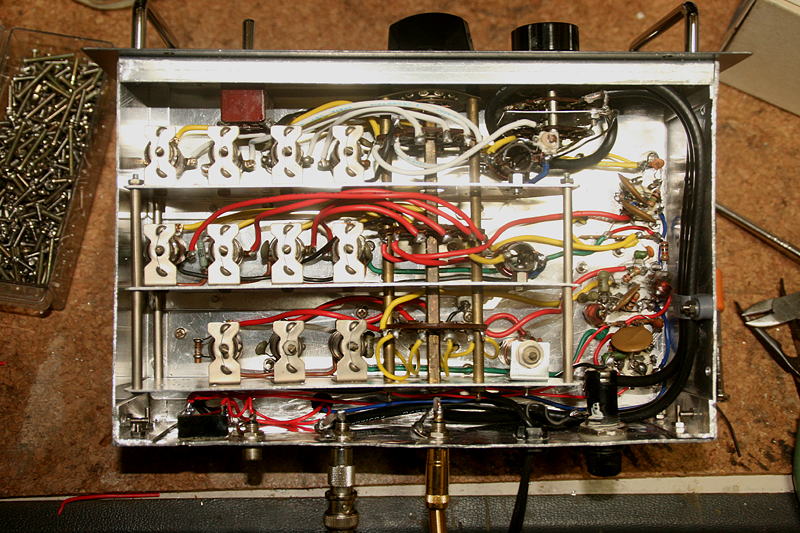
All the work has been completed now. I felt relieved to see the workd for 50MHz had been done well. As far as I confirmed with the grid dip meter, it seems to work properly, overcoming problem of long wiring for switching.
I gave it a try to connect it to the YAESU FT-817 being set to 3.5MHz. Oh, there you are! I can hear many signals! Yes, these are CW and SSB on 7MHz! I tried to change the band switch of the convertor to 14, 21, and 28, and I could monitor FB signals coming in at all bands!
The sensitivity is good enough. Now the receiver(MAFRX-35A) can work as a double super heterodyne all band receiver.
As the crystals for 50MHz have not been arrived yet, there is no way to confirm the function for 50MHz, but I'm sure it will. I did an adjustment of cores of each coils, but everything is over very simply and quickly at the end of the project.
Now the crystal for the high bando for 28MHz and two crystals for 50MHz were arrived.
Of course, a case of HC-6U size is no longer available, and ordered crystals are manufactured in a HC-49 size.
I wanted them to be in a HC-6U size, which used to be a very common in 1960's to 1970's.
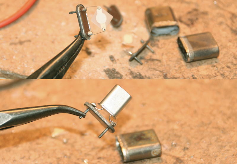
Giving a heat with a gas burner to melt the solder at joinning area of disuse old HC-6U to took them apart. Take out the crystal plate and other parts and put a HC-49 with its leads shortened, and solder the leads to the terminals. After that covered the case and soldered joinning area.
Thus I modified a HC-49 into a HC6U.
Upper picture shows the crystal plate is sandwitched with a metal terminal in the HC-6U. Lower picture shows where the modified HC-49 is reborn as a HC-6U.
Now the last crystals are ready to go. I opend a convertor which had been already set in my shack, and inserted crystals. Well, how about it? I kicked on the power without any adjustment to see what go'na happen first. Gee, signals of 50MHz band coming through with out any adjustment! It's too quick...
Excellent! I was worrying about the band switching including VHF band, but even I compared with my reference radio IC-756PRO3, signals can be heard almost the same way.
Oh, Yes! Suddenly I realized that all the big project (3.5 to 50MHz AM/CW 10W Transmitter and Receiver Line) is over!
At last, everything is over with success!
I planed the idea of the project on last July 29th, so it's been three months to realize it all.
I think I did it well.
This is the final version of the circuit diagram. If you need detailed image, please download the PDF file from here.
 In case you hit this
page directly from a Search Engine, you can reach to all of the pages of MAFNET from Top Page
In case you hit this
page directly from a Search Engine, you can reach to all of the pages of MAFNET from Top Page