[The last renewal of this page: November 7, 2010]
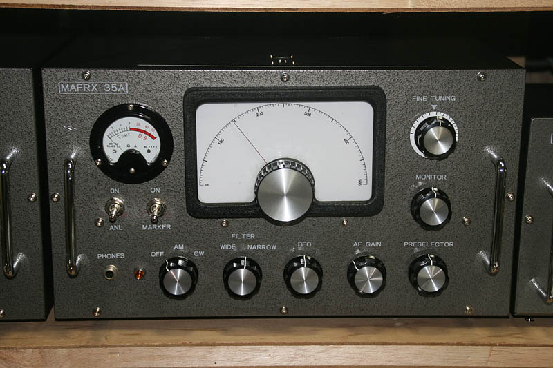
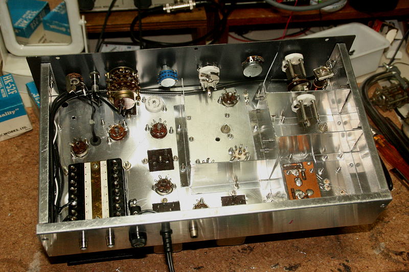
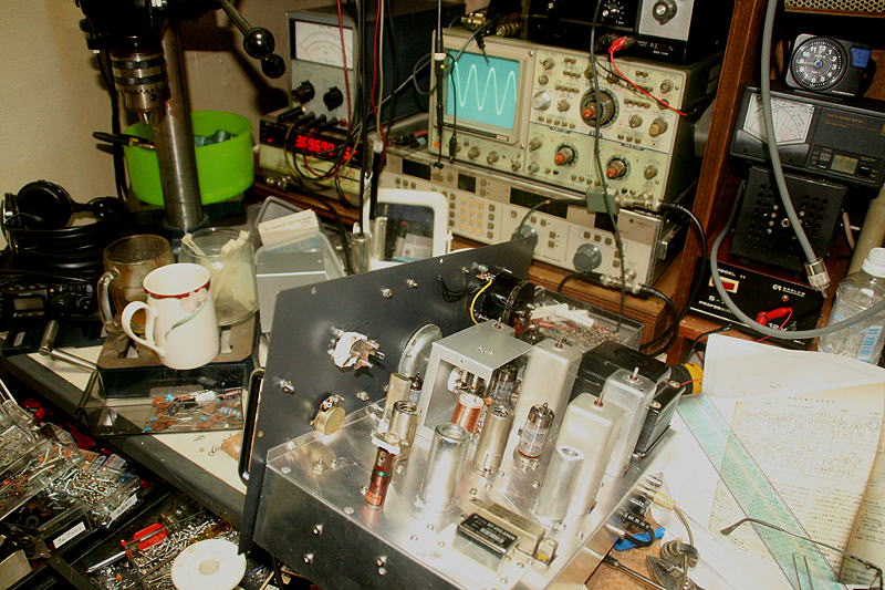
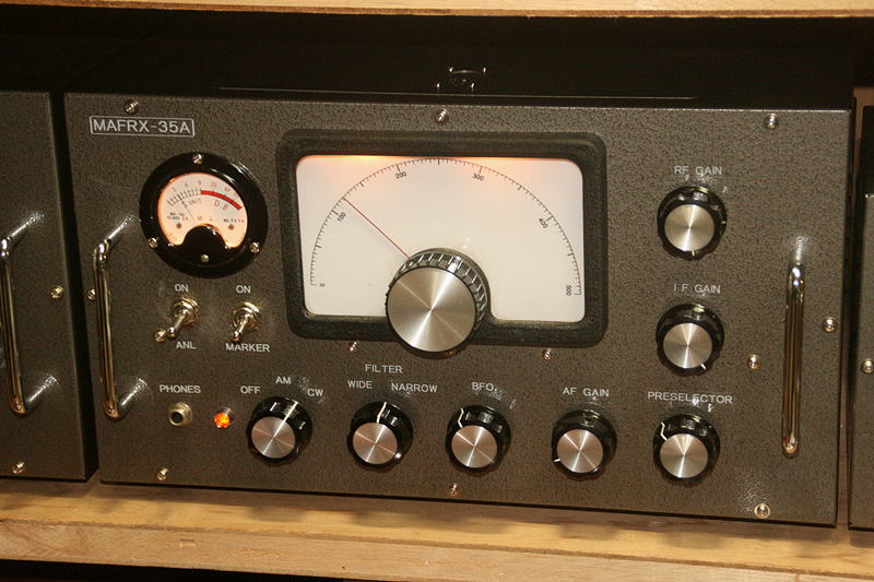
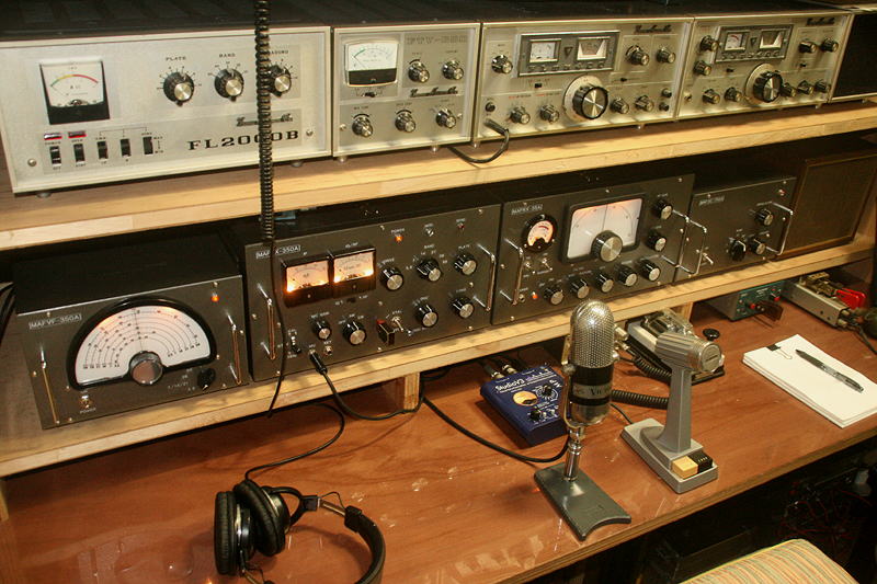
I decided to build a single super receiver from 3.5MHz to 4.0MHz, and a crystal controled convertor for 7/14/21/28/50MHz to compose a receiving system.| Receiving Frequency | 3.500MHz`4.000MHz |
| Receiving Mode | AM/CW(SSB) |
| IF Frequency | 455KHz |
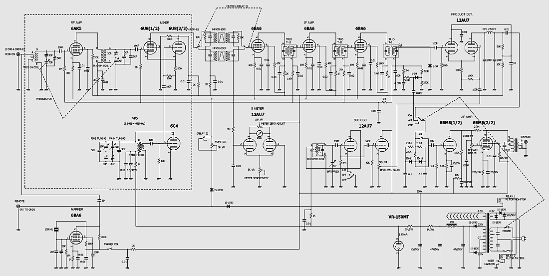
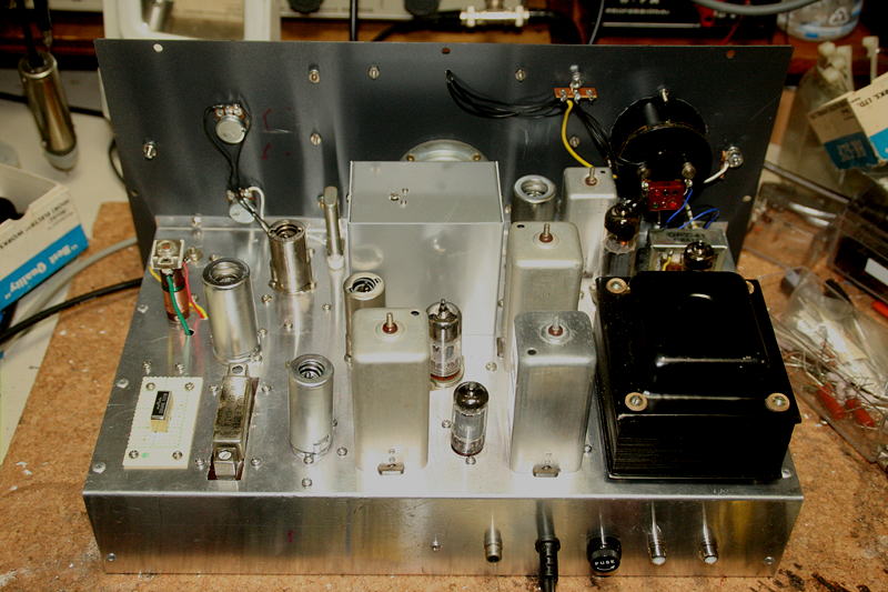
| Structure of amplifire | RF1+IF3 |
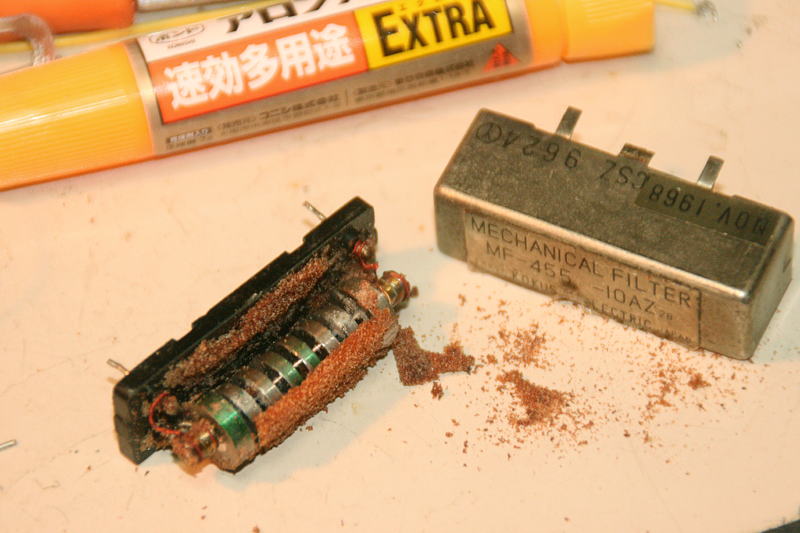
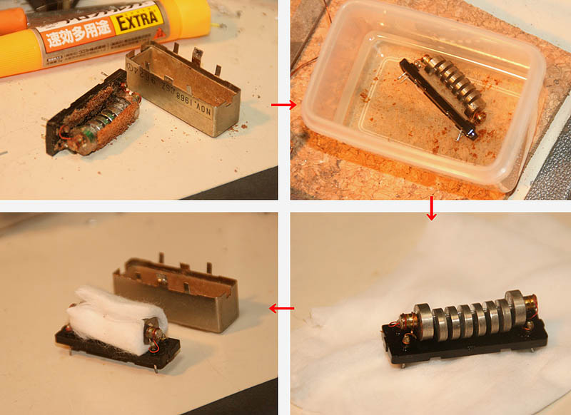
| Selectivity Measure | Mechanical filter for SSB (with a Q-dump rsistor), and a Crystal filter for CW (500Hz) |
| Detection | Product Detection |
| BFO | Varialble with a BFO coil |
| Noise Measure | ANL with diodes |
| Frequency Calibration | 100KHz Marker |