All tube 50MHz AM/FM/CW heterodyne Transmitter (MAFTX-50A)
- Built in 2010 -

[The last renewal of this page: September. 17, 2010]
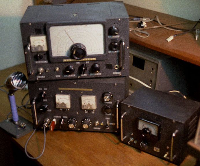
The picture below is an old homebrew 50MHz transmitter and receiver which I build when I was a senior high student in the 1960's. The transmitter had a 2E26 for the final providing 10W output with 6BQ5 push-pull AM modulator(Plate-Screengrid Mod.), and Variable Capacitor was used for FM modulation at the VFIO. The receiver was RF1+IF2 and a crystal converter was built in. I used to be crazy about enjoying ragchews every night with this setup. This is such an old and excellent equipments, however to my regret, I threw them away later, and are not with me now.
As I get age, I became missing them and getting impossible to forget them. I became to think to if I could rebuild them again.
Fortunately, the AS-1 cabinet is still in the market although it has passed forty years by now. However, there is no way to find the vernier dial with a scale board like MITSUMI's MD-5 in the market anymore. There was another idea that it does not look smart to try to get the old girl friend, who I have thrown away before, back again.(hi hi) So I decided to build a senior version of them with holding old sweet memories just in my heart.
Although a regular AM transmitter get the target frequency by multiplying the original osilated frequency, for the 50MHz band, it is hard to get the stability of the frequency, and this was the weak point of homeberw AM transmitter.
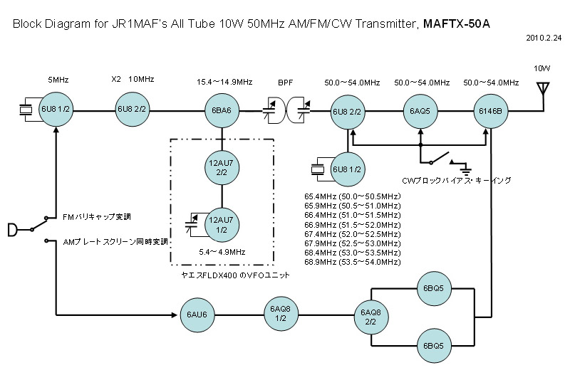
So, for this transmitter, I designed to mix the crystal controlled local oscilater's frequency to the 5MHz VFO output to get 50MHz.
My idea is to use the VFO unit using a single 12AU7 which I took apart from old YAESU SSB transmitter, FLDX400, to get the stability of the frequency as high as a SSB radio.
This system allows me to use this transmitter for transceive operation with the receiver which I am going to build using the same VFO unit. This will be a great feature of this system.
On the other hand, for FM modulation, multiplying frequency help the frequency modulation modulated by varicap over the crystal to get the enough frequnency deviation, so the system without multiplyig will be a problem. So, in this system I designed to get the local oscilation frequency by multiplying(X6) the crystal oscilator for lower frequency which is modulated by varicap to resolve this problem.
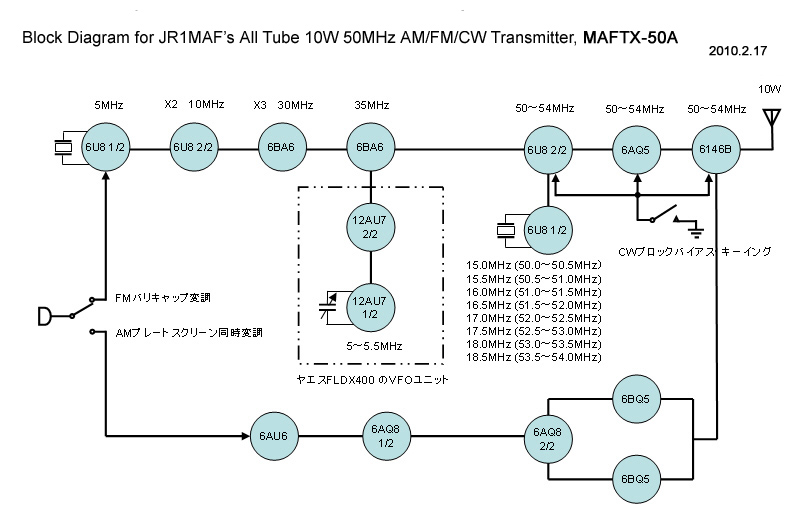
This is ablock diagram oh this transmitter.
My idea is not to use much money for homebrew equipments. If you use high-grade brandnew parts, it will be an artistic product, and so nice, however, I think the best way to go for amateurs is "inventiveness and originality". Use of junk and useless article, recycling are what the time is requesting us now. That's absolutely repersenting this ECO-era.
To start with, I purchased a junk of 40 years old TRIO AM transmitter TX-88D. With only couple of thouand Yen(US$50.00), I could get
a various valuable pars such as a cabinet, a power transformer, a modulation transformer, relays, rotary switches, and etc.
As I mentioned before, I used a VFO unit from 50 years old YAESU SSB transmitter FLDX400 with its gear dial mechanism.
I also used a shield case of the final tank circuit, coil bobines with core, and some other small parts from the junk of FLDX400.

This is a schematic diagram of this transmitter. I studied taking many hours, and I decided star the thing from this diagram.
Took apart TRIO TX-88D right after it arrived at my home after getting it at very cheap price in the Yahoo Auction.
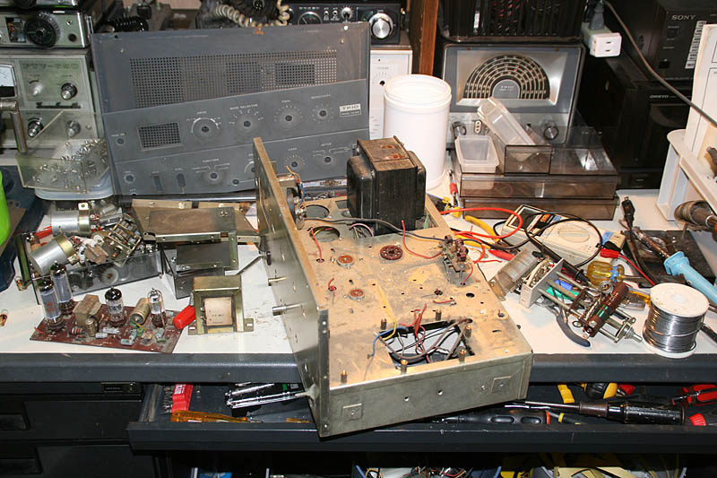
Wash with water the chassis from which all the parts took away. Then, cut the upper surface of the chassis with the power jig-saw. Considering the strength of the left part of the chassis for the heavy power transformer, firstly cut in square in the center part of the chassis.
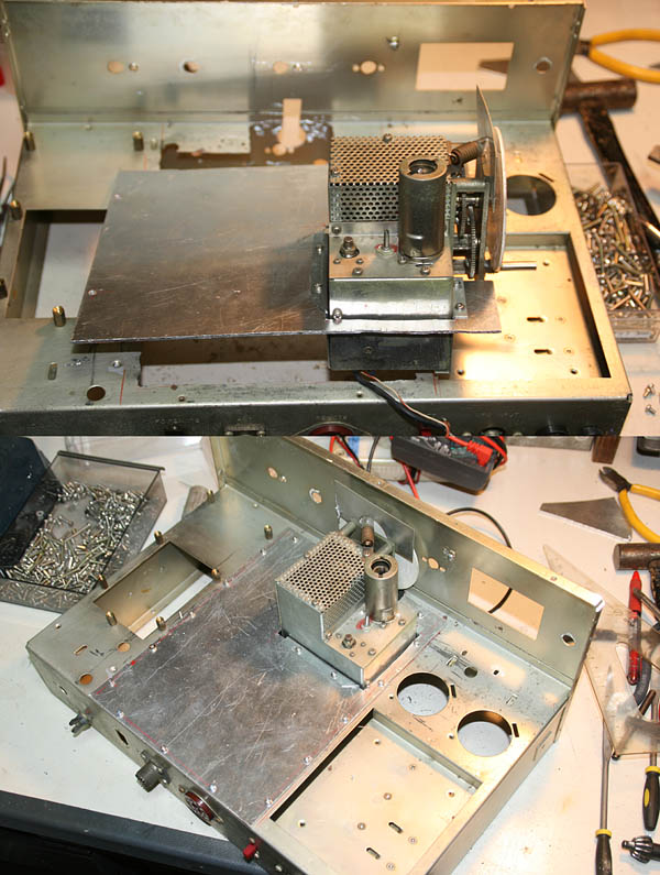
Put an aluminum panel with a thickness of 1.6mm over the sqaure hole. Thus, the chassis reborn in new.
Mount the VFO unit from the junk of YAESU FLDX400. It should be set down from the chassis. Make a mounting bracket with aluminum plate and mount it to the chassis.
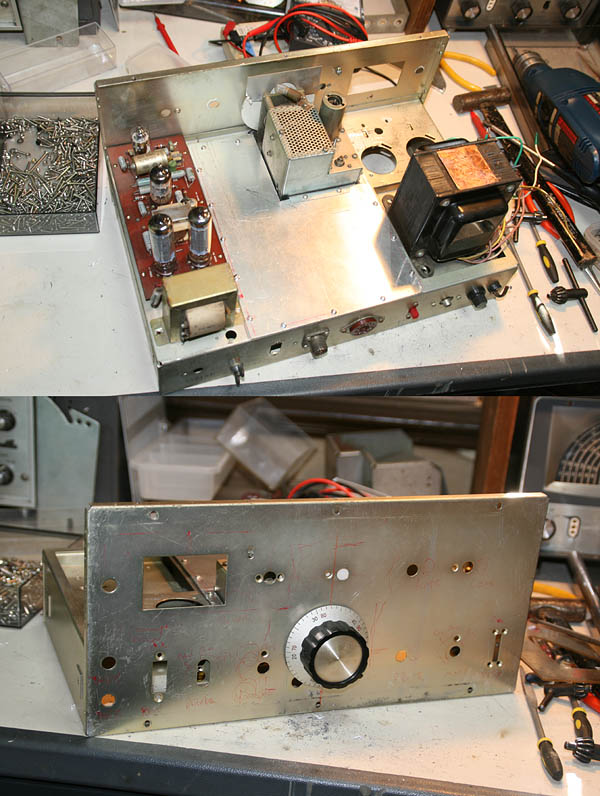
To check the layout, palce the power transformer and a modulator unit(no intension to use this unit) using 6BQ5 push-pull for TRIO TX-88D.
Opened the space for the meter and the daial window.
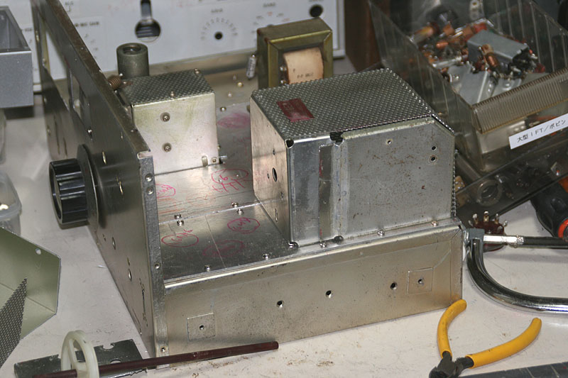
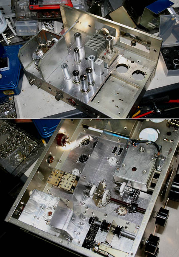
The shield case for final stage, I used the one from FLDX400 after cutting it and resizing it smaller.
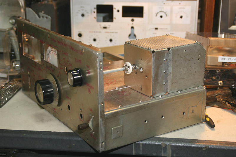
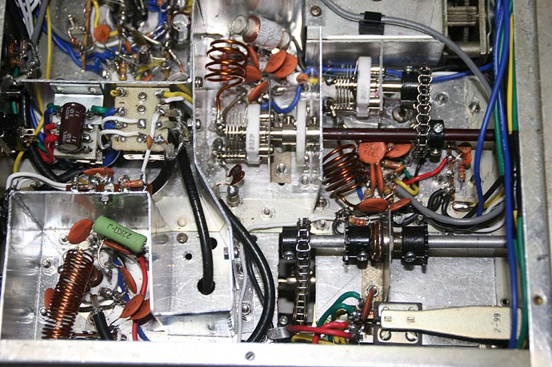
Now PLATE VC is operable from the front panel, but there is no way to operate the LOAD VC.
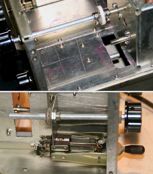
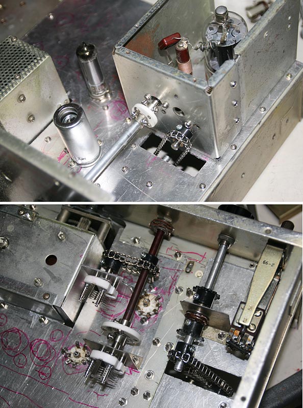
After the examination, I decided to use the chain and sprocket (being detached from TRIO TS-520) being sold in the YAHOO Auction. With these parts, it is possible to operate the LOAD VC from under the chassis.
For the axis supporter, I used an old headphones jack.
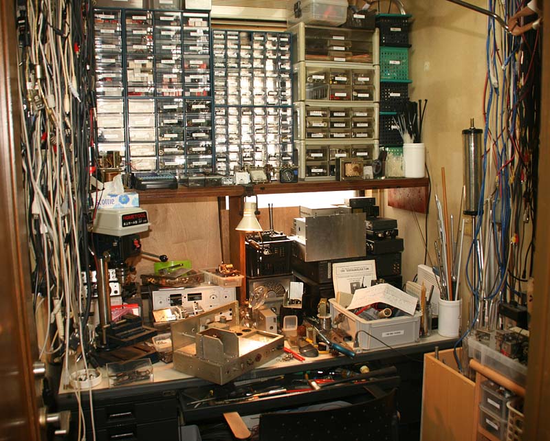
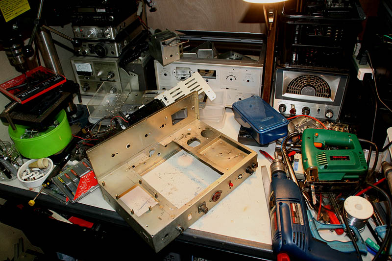
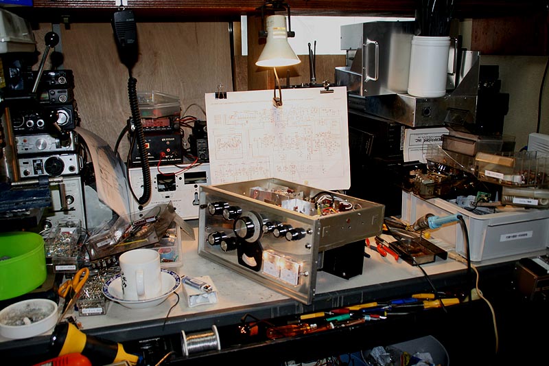
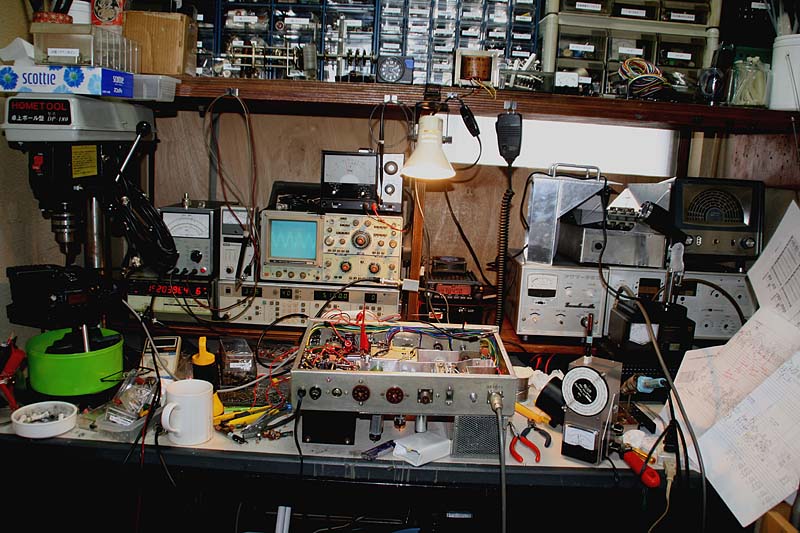
This is my factory.
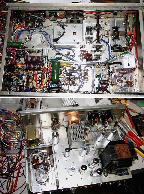
The 0chains system for the LOAD VC works well. Another problem is to syncronize two VCs in driver stage, and I needed two nights for the examination. The conclusion is what you see in this picture.
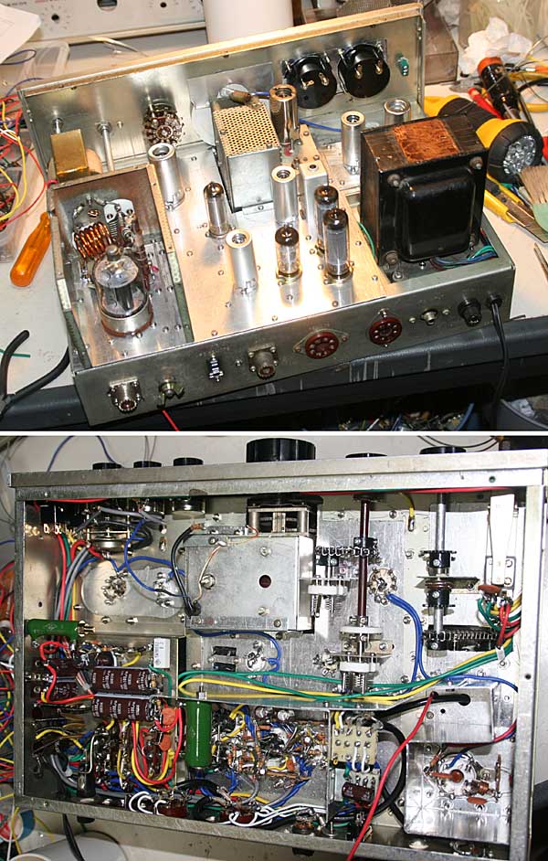
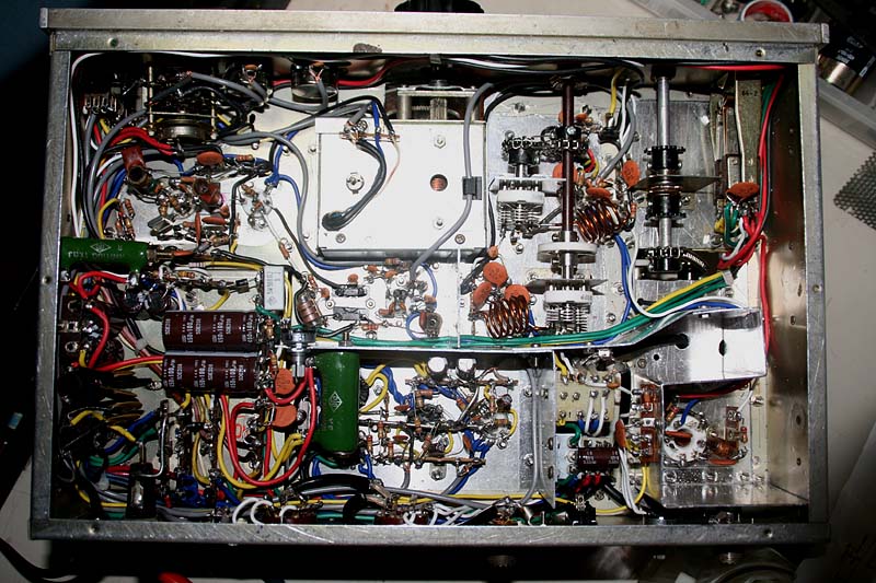
Mounted the tubes, shield plates inside the chassis, and the relays. Due to the limit of the space, and the existance of the VFO unit just in the middole of the good space, good considerations were required for layouting the parts and shield plates.
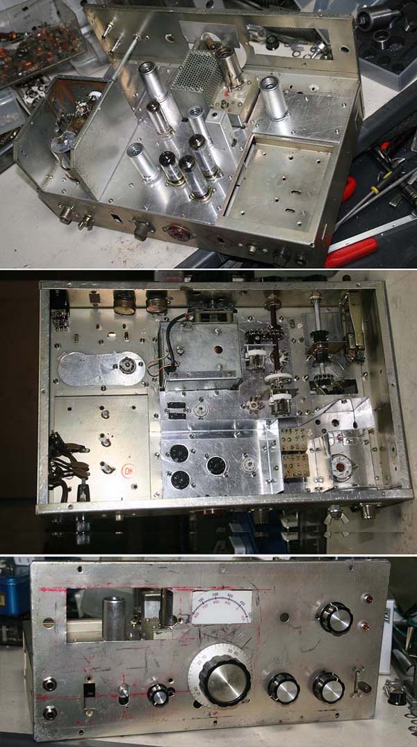
After all, I needed to release the space for the block capacitors near the power transformer for hte circuit. To maintaine the strengthe of the chassis, hole to be cut was limitted to the minimum size to mount an aluminum panel over it.
Recently, the electrolytic condensers have gotten much smaller, and the block type capacitor is not necessarily necessary anymore. I used small lead type capacitor instead, and mount them under the chassis.
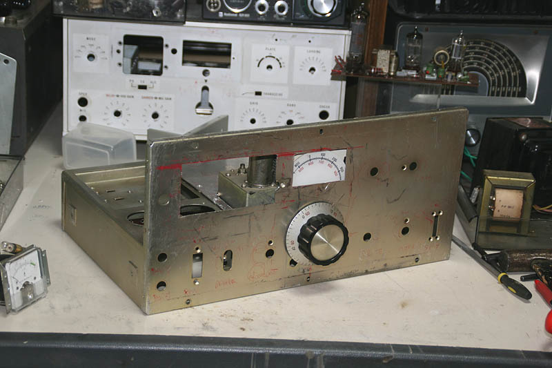
Front panel is getting show its final appearance.
I mounted an aluminum panel of 1mm thickness over the steek panel to dress it up. Meters have been installed. Meters are mounted to the aluminum panel directly, and the Siemens key is mounted to the steel panel. Other parts are mounted and tightned sandwiching both panels together.
I repeated failures for two days, but finally succeeded to make an escussion plate grinding aa aluminum plate of 2mm thickness using a hand grinder. Its design is something like one between YAESU SSB transmitter FL-100B and STAR SSB transmitter ST-700, and looks very nice.
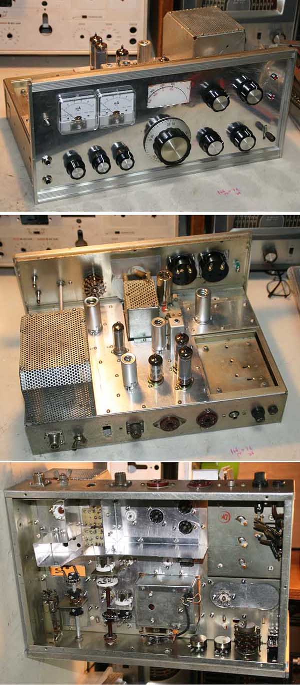
Now, wiring is started. Firstly the power supply circuit and modulator circuit. After that, I mounted relay circuit, and then I confirmed the basic functions. (As the important power transformer and relays are junk parts, it is better to confirm if they work or not here.)
Wiring for the RF circuit is started. No space and a difficult layout require me a lot of time for consideration.
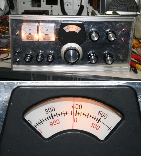
For the rest for a while, I made a transparent cursor plate for the dial window. I scratched an acrylic fiber palte to make a line with a cutter knife, and poured a red ink with a red felt pen to put it on the dial escussin from the back. This was very succesful.
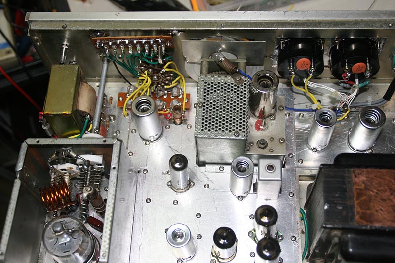
I mounted a local oscilator circuit. For the time being, a crystal bought in Akihabara for 600Yen(US$6.00) is installed. (For 50.0-50.5MHz band)
As I could not find a space, I mounted a rag-plate to the back of the steel panel soldring a metal spacer to the panel. (A steel panel requires us to work hard for driling holes, but it is convenient for soldering.) For the oscilator coil, I used one of the junk coils being detached from FLDX400 without any modification.
I'm afraid for missing wirings, but anyhow, all the wirings have been completed!
I will work later for binding wires, and other decorations. It's better to leave it for unexpected troubles in adjusting process, including the case of change of the circuit.
Kick on the fire now!
Before doing it, I cleaned the desk first and a deep respiration. I prepared for emergency escape from the factory (I used to do this everytime I kick on the fire at the 1st time when I was a student, hi hi.), and then, insert the AC plug to the AC outlet.
Mm? You ask me if I checked and confirm the wiring? Oh, that's the very fundamental action, you bet! No, I did not!
Well, I have cheked in in every step of wiring, and power supply was cheked already, then....It's a single-bout match! Hey, Boy be brave!
Switch ON!
Turn away the face! Get away!!
Huum, No sudden explosion... All the heaters are warmed up, but no smoke is observed. No smell, no vibrations.
Okay, then give it a try to transmit!
The relays sounds great. The IP meter shows a little bit current is going. (What's the world the current goes such little? The C class should allow the IP flow more.... Well it's Okay for now...)
Nobody would do like this at once without any checks. But, it's Okay, nothing worse could not happen.
So, I switched off the power, and will be back here for checking and adjusting after going outside for shopping, and cool down my brains.
I found a terrible self oscilation going! I inserted as many by-pass capacitors and RFCs as possible. The I rewired heater lines, bias lines and modulator transformer lines. I also installed shield panel between each sections, and changed ground point of shield wire between 6AQ5 and 6146. However, nothing was improved and the cause was kept uncertain for a couple of days. After all, the problem was resolved when I replaced the RFC for the grid of 6146 from a commercial made RFC of 2.5mH to homebrew coil of 30 turns.
I traced RF signal from the heterodyne section, and I checked the RF of 50MHz was generated. Only the problem seems to be the fact that the RF level after the last heterodyne(35MHz+15MHz) was not high enough to drive the power section in C class.
During these adjsutment work, I recognized that I made a fatal mistake in frequency composition because of possible spurious being generated.
More over, the VFO unit from FLDX400 has a reverse dial aginst its oscilated frequecy(0 to 500KHz on the dial generate 5.4 to 4.9MHz), and what is required is a minus heterodyne instead of a plus heterodyne. I have to re-design totally. I am examinning it now, and I can understand the designers of radio maker always spend a hard time to design frequncy composition. It's so complicated! If you get this one, then you lose that one, and it's so difficult to get all together.
I am not sure that this is the best idea or not, but I decided to bring the frequency of the local oscilator to higher than 50MHz, like this.
This requires me the minimum change from the current circuit, anyway.
5MHz of Base osilator could be better to be changed to 10MHz to avoid any conflicts with VFO's frequency, however, this could be easily done later. Considering to get enough frequency deviation for FM, I decided to try this way first.
I ordered crystals for 65MHz level in 3rd overtone.
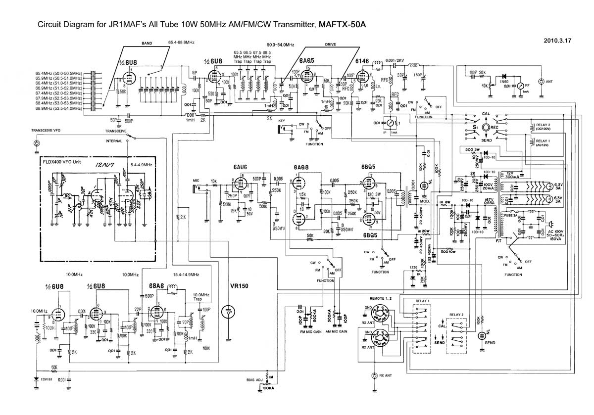
This is the current schematic diagram after many changes and adjustment. It looks very different from the original one.
The crystal that I ordered arrived now, and I started modification and adjustment.
To fight against equipment with heterodyne circuit, I recognized that I surely need measuring instruments, so taking this opportunity, I moved all the measuring instruments from my shack to my factory room.
It is not an easy work to change the schematic diagram after completing all the wirings for original one. Very difficult to get required space, signal flow line can not be ideal, and a complete shielding is also very difficult. Difficult probrems are piled up in front of me!
I gave up 5MHz for the base local oscilator, expecting that I could find the other way to generate a good FM modulation, and used 10MHz crystal.
I learned many spuriouses can be easily generated under double conversion system (if I mistake adusutments), and filters are importand as well as getting adequate mixing levels. So, I decided to take time to work hereafter step by step.
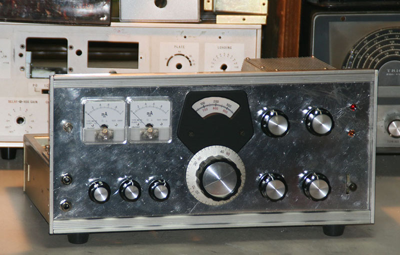
Except relacing front panel to finished up one with lettering work, assembly work has been completed and finished here.
 In case you hit this
page directly from a Search Engine, you can reach to all of the pages of MAFNET from Top Page
In case you hit this
page directly from a Search Engine, you can reach to all of the pages of MAFNET from Top Page