Know-How for Cooled CCD Camera (SBIG/ST-7)

[The last renewal of this page: Aug. 28, 2001]
1. Build an AC Power Supply
I beleive so many peoples are using SBIG's ST-7, however, very few of them must have
both AC Power Supply(for AC 100/117V Powerline at home) and DC Power Supply(for
Battery's DC12V).
DC Power Supply is fancy when we go out looking for a clear sky, however, if you use
the camera at home, in your base observatory, it is not recommendable as it requires
another Stabilized DC Power Supply for 12V for giving input source to it.
To make the matter worse, in many cases, cheap Stabilized DC Power Supply dose not have output
voltage adjustment, and the output voltage is fixed to 13.8V, which is the same
volatage of automobile DC powerline.
If you keep using this source for ST-7's DC Power Supply, sooner of later, it maybe damaged.
It seems to be designed strictly for DC12V, leaveing very little margin.
Well. then, here I am going to introduce you a fantastic method to build your own
AC Power Supply with little cost, almost none, using a power supply unit of old personal
computers which you may find anywhere as garbages nowadays.
ST-7 has a logic circuit just the same as a comuputer, and the voltage needed should
be the same as a personal comuputer.
First of all, remove the top case of computer. That is easy, as easy as you only need
a single screw driver.
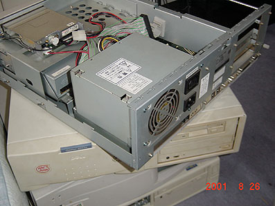
The top of panel fo the cabinet of power supply may indicates available voltages and
relative current capacities. +5V -5V +12V -12V may be foound there.
ST-7 requires following volateges and currents.
1. + 5V 2.0A
2. -12V 0.1A
3. +12V 0.5A

Current capacity should be checked, however, all the normal personal comuputers may
cover these requirements.
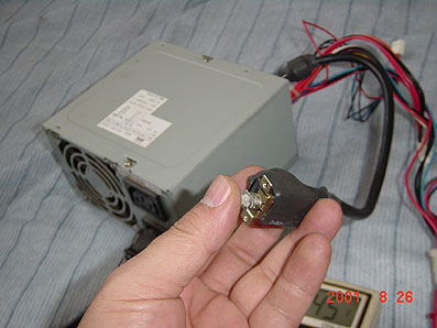
Power supply with the cable being wired to the Power Switch of the computer at its
front panel is highly recommended. The one which the said switch is wired to the
motherboard, not directly to the power supply, is controlled through the motherboard
and is not easy to be modified for this case.
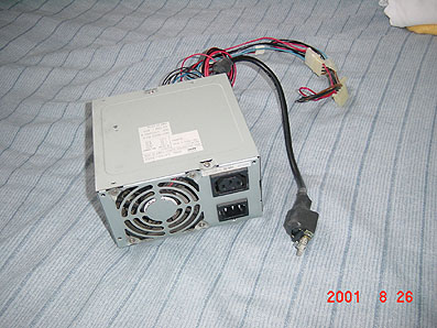
Well, open the cover of the unit first!
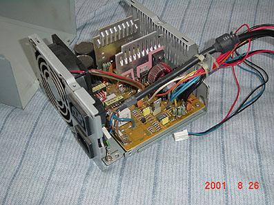
Colorful wires may get you worried about, but take it easy! Most of them are coming
out of the same point of the circuit board. They are principaly devided into five
lines only as follows;
1. COMMON (Ground for output powerline)
2. +5V
3. -5V
4. +12V
5. -12V
Cut them shorter away.

If you cafully watch the surface of the circuitboard, where the wires come out, you may
find the polarity and volatege are printed in most cases.
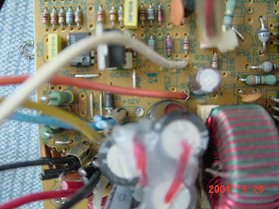
A couples of wires are coming out from the same point...

Leaving only one for each point, cut away the rest of the wires.

ŽŸ‚ɔ핞‚ð”�‚¢‚Ä“dˆ³‚ðƒ`ƒFƒbƒN‚Å‚«‚é‚悤‚É‚µ‚Ü‚·�B
“dŒ¹•”‚Ƀpƒ\ƒRƒ“‚Ì“dŒ¹ƒP�[ƒuƒ‹‚ð�·‚µ�ž‚ñ‚Å�A“dŒ¹•”‚©‚ç�o‚Ä‚¢‚éƒXƒCƒbƒ`�i•�’Ê‚ÍŒJ‚è•Ô‚µ‰Ÿ‚·
‚ÆON-OFF‚ðŒJ‚è•Ô‚·ƒ^ƒCƒv‚¾‚ÆŽv‚¢‚Ü‚·�j‚ð‘€�삵‚Ä“dŒ¹‚ðON‚É‚µ‚Ü‚·�B
‚±‚ê‚Å“à‘ ‚̃tƒ@ƒ“‚ª‰ñ‚èŽn‚ß‚ê‚Î�A“dŒ¹‚Í—§‚¿�オ‚Á‚Ä‚¢‚Ü‚·‚ª�A‚Ü‚ê‚Ƀtƒ@ƒ“‚ª‰ñ‚ç‚È‚¢�ê�‡‚ª
‚ ‚è‚Ü‚·�B�@‚±‚ê‚Í�o—Í‘¤‚É‚È‚É‚à‚‚Ȃª‚Á‚Ä‚¢‚È‚¢�i–³•‰‰×�jˆ×‚É‹N‚±‚錻�Û‚Å‚·‚Ì‚Å�A‚»‚Ì�ê�‡
‚Í‚Æ‚è‚ ‚¦‚¸ƒeƒXƒ^�[�iDC“dˆ³‚Ì�”�\ƒ{ƒ‹ƒg‚̃Œƒ“ƒW‚É‚µ‚Ä‚¨‚�j‚ð�•ƒŠ�[ƒh‚ð“dŒ¹•”‚Ì�•‚¢�ü�A�Ô
ƒŠ�[ƒh‚ð�Ô‚¢�ü‚É‚ ‚Ä‚½�ó‘Ô‚Å�A“dŒ¹ƒXƒCƒbƒ`‚ð“ü‚ê‚Ü‚·�BƒeƒXƒ^�[‚Ì“à•”’ï�R‚ª‚킸‚©‚È•‰‰×‚Æ‚È
‚Á‚Ä“dŒ¹•”‚Í–³Ž–‚É—§‚¿�オ‚é‚Í‚¸‚Å‚·�B�i—§‚¿�オ‚Á‚Ä‚µ‚Ü‚¦‚Î�AƒeƒXƒ^�[‚ð‚Í‚¸‚µ‚Ä‚à“dŒ¹‚ÍŽ~
‚Ü‚è‚Ü‚¹‚ñ�B�j
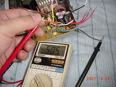
ƒeƒXƒ^�[‚Ì�•ƒŠ�[ƒh�ü‚É“dŒ¹•”‚Ì�•‚¢�ü‚ð�‚µ‰i‚߂ɔ핞‚ð”�‚¢‚ÄŠª‚«‚‚¯‚Ä‚¨‚«‚Ü‚·�B‚»‚µ‚ăeƒX
ƒ^�[‚Ì�ÔƒŠ�[ƒh‚ÅŽŸ�X‚É“dŒ¹•”‚©‚ç�o‚Ä‚¢‚éŠe�F‚Ì”z�ü‚É‚ ‚Ä‚Ä“dˆ³‚Æ‹É�«‚ðƒ`ƒFƒbƒN‚µ‚Ü‚·�B
ƒpƒ\ƒRƒ“‚Ì“dŒ¹‚͈ӊO‚Æ‚¢‚¢‰ÁŒ¸‚Å�AƒP�[ƒX‚É�‘‚¢‚Ä‚ ‚é“dˆ³‚©‚畽‹C‚Å�{�|‚P‚O�“‚‚ç‚¢‚ÌŒë�·‚ª
‚ ‚è‚Ü‚·‚ª�A‚±‚Ì’ö“x‚ÌŒë�·‚Å‚Í‹@Ší‚Ƀ_ƒ��[ƒW‚ð—^‚¦‚鎖‚Í‚È‚¢‚Ì‚Å‹C‚É‚µ‚Ü‚¹‚ñ�B�i�Î�j
ST-7‚܂ł̃P�[ƒuƒ‹—p‚É‘½�cƒP�[ƒuƒ‹‚ð—pˆÓ‚µ‚Ü‚·�i�Å’á‚T�c•K—v‚Å‚·�j�@
�H—tŒ´‚È‚Ç‚ÅŠÈ’P‚ÉŽè‚É“ü‚è‚Ü‚·�B‚ ‚Ü‚è�ׂ¢‚à‚Ì‚Í“d—¬—e—Ê‚ª‚È‚“dˆ³�~‰º‚ð�µ‚‚Ì‚Å�A“K“–‚È
‘¾‚³‚Ì‚à‚Ì‚ð—pˆÓ‚µ‚Ü‚·�B
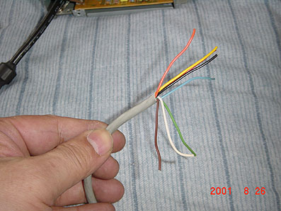
”z�ü‚𑵂¦‚Ĕ핞‚ð”�‚¢‚Ä�A‚Í‚ñ‚¾•t‚¯‚Å�Ú‘±‚µ‚Ü‚·‚ª�A”MŽû�kƒ`ƒ…�[ƒu‚ð‚ ‚ç‚©‚¶‚ß2cmˆÊ‚É�Ø‚Á
‚Ä’Ê‚µ‚Ä’u‚«‚Ü‚·�B�@
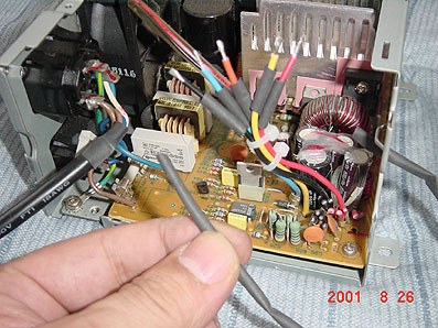
‚Í‚ñ‚¾•t‚¯Œã�A‚¸‚炵‚Ä‚Í‚ñ‚¾•t‚¯•”‚𕢂Á‚Ä‚©‚烉ƒCƒ^�[‚ ‚Ô‚é‚Æ�A
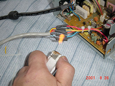
‚ ‚Á‚ÆŒ¾‚¤ŠÔ‚Ƀsƒbƒ^ƒŠ‚ÆŽû�k‚µ‚Ä�â‰�‚µ‚Ä‚‚ê‚Ü‚·�B�i‚È‚¢�ê�‡‚̓rƒj�[ƒ‹ƒe�[ƒv‚ðŠª‚¢‚Ä‘ã—p‚µ
‚Ü‚·�j‚±‚Ì”MŽû�kƒ`ƒ…�[ƒu‚à�H—tŒ´‚Ì”z�ü�Þ‰®‚³‚ñ‚Å�AŠÈ’P‚ÉŽè‚É“ü‚è‚Ü‚·�B
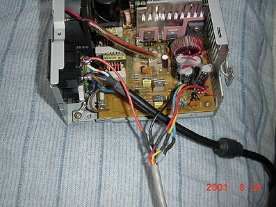
�Å‘å‚Ì“ïŠÖ�i�H�j‚Í‚±‚ê‚©‚ç‚Å‚·�B�@ST-7‘¤‚̃RƒlƒNƒ^�[‚ÌŽæ‚è•t‚¯‚Å‚·�B
¢DINƒvƒ‰ƒO‚̃IƒX‚Ì5ƒsƒ“£‚ð—pˆÓ‚µ‚Ü‚·�B�i‚±‚ê‚à�H—tŒ´‚Å‚·‚Ë�I�j
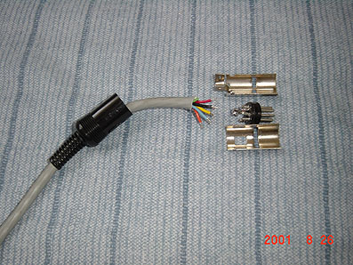
ŽÊ�^�iŒãŒf�j‚ð—Ç‚Œ©‚Ä�A�Ú‘±‚ðŠÔˆá‚¦‚È‚¢‚悤‚É�A‚»‚µ‚Ä‘ŠŒÝ‚É�Ú�G‚µ‚È‚¢‚悤‚É�×�S‚Ì’�ˆÓ‚ð•¥
‚Á‚Ä‚Í‚ñ‚¾•t‚¯‚µ‚Ü‚·�B ‚Í‚ñ‚¾•t‚¯‚·‚é‘O‚É�A•ª‰ð‚µ‚½ƒRƒlƒNƒ^�[‚Ì–{‘Ì�i‚ÆŒ¾‚¤‚©�•‚¢ƒvƒ‰ƒXƒ`
ƒbƒN‚Ì•”•ª�j‚ðƒP�[ƒuƒ‹‚É’Ê‚µ‚Ä‚¨‚‚Ì‚ð‚¨–Y‚ê‚È‚�B�iŒã‚ő勃‚«‚·‚é‚Í‚ß‚É‚È‚è‚Ü‚·�j
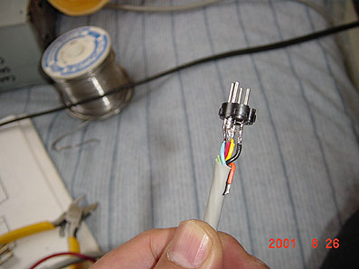
”z�ü‚Ì‚¤‚¿ˆê–{‚Í‹à‹ï‚Ì�ªŒ³‚É‚Í‚ñ‚¾•t‚¯‚µ‚È‚¯‚ê‚΂Ȃè‚Ü‚¹‚ñ�B�i�M�†‚̃A�[ƒX�j
‚±‚±‚ŃP�[ƒuƒ‹‚Ì”z�ü‚ð�®—�‚µ‚Ä‚Ý‚Ü‚·
‚P�D�M�†‚̃A�[ƒX “dŒ¹•”‚̃P�[ƒX �¨�@ƒRƒlƒNƒ^�[‚Ì‹à‹ï‚Ì�ªŒ³
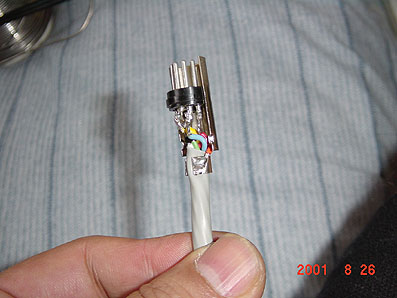
‚Q�D“dŒ¹‚̃A�[ƒX “dŒ¹•”‚ÌCOMMON �¨�@ƒRƒlƒNƒ^�[‚ÌŽÊ�^‚̃sƒ“
‚R�D-12V “dŒ¹•”‚Ì-12V �¨�@ƒRƒlƒNƒ^�[‚ÌŽÊ�^‚̃sƒ“
‚S�D+12V “dŒ¹•”‚Ì+12V �¨�@ƒRƒlƒNƒ^�[‚ÌŽÊ�^‚̃sƒ“
‚T�D+5V “dŒ¹•”‚Ì+5V �¨�@ƒRƒlƒNƒ^�[‚ÌŽÊ�^‚̃sƒ“
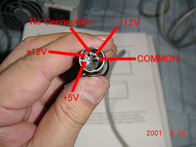
‚±‚Ì”z�ü‚ª‚Å‚«‚½‚ç�A‚à‚¤Š®�¬‚µ‚½‚à“¯‘R‚Å‚·�B
‚¹‚Á‚©‚‚¾‚©‚ç�A“dŒ¹•”‚©‚çƒXƒCƒbƒ`‚ªƒuƒ‰ƒuƒ‰‚µ‚Ä‚¢‚é‚Ì‚Í‚¢‚©‚É‚àŠi�D‚ªˆ«‚¢‚µ�A‘€�ì�«‚à—Ç‚
‚ ‚è‚Ü‚¹‚ñ‚Ì‚Å�A“dŒ¹ƒXƒCƒbƒ`‚ðƒP�[ƒX‚ÉŽæ‚è•t‚¯‚Ä‚µ‚Ü‚¢‚Ü‚·�B
ƒXƒCƒbƒ`‚Í‚È‚ñ‚Å‚à‚¢‚¢‚Ì‚Å‚·‚ª�A�¬‚³‚ȃXƒiƒbƒvƒXƒCƒbƒ`‚ª�i‚±‚ê‚à�H—tŒ´�jƒhƒŠƒ‹‚ÅŠJ‚¯‚錊‚à
�¬‚³‚‚Ä�H�삪Šy‚Å‚·�B
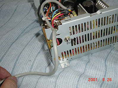
“dŒ¹ƒXƒCƒbƒ`‚Ì”z�ü‚Í�A‹@Ší‚É‚æ‚Á‚Ä‘½�ˆá‚¢‚Ü‚·‚ª�A‚±‚±‚Ü‚Å�ì‹Æ‚Å‚«‚½•û‚È‚ç�A‚¶‚Á‚Æ’‚ß‚Ä‚ê
‚΂킩‚é‚ÆŽv‚¢‚Ü‚·�B�@—v‚̓Rƒ“ƒZƒ“ƒg‚©‚ç“ü—Í‚³‚ꂽAC100V‚Ì‚¤‚¿�A•Ð•û‚¾‚¯‚ð�Ø‚Á‚½‚èŒq‚¢‚¾‚è
‚·‚ê‚΂¢‚¢‚Ì‚Å‚·‚©‚ç�B
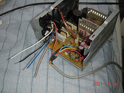
—v�Š—v�Š‚ðƒoƒCƒ“ƒh�ü‚È‚Ç‚Å”›‚Á‚ČŒ肵‚Ü‚·�B�@‚±‚¤‚µ‚Ä�A�‹‚É—§”h‚È“dŒ¹‚ªŠ®�¬‚Å‚·�B
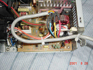
Š®�¬‚µ‚½‚ç�Q‚Ä‚È‚¢‚Å�AƒRƒlƒNƒ^�[‚̃sƒ“‚ɃeƒXƒ^�[‚ð‚ ‚Ä‚Ä�A”z�ü‚ªŠÔˆá‚¢‚È‚¢‚±‚Æ�A‹É�«“dˆ³‚ª
�³‚µ‚�o‚Ä‚¢‚邱‚Æ‚ðŠm”F‚µ‚Ü‚·�B�@ƒsƒ“‚ÌŠÔŠu‚ª‹·‚¢‚̂ŃVƒ‡�[ƒg‚µ‚È‚¢‚悤‚É‹C‚ð‚‚¯‚Ä�A�T�d
‚Ƀ`ƒFƒbƒN‚µ‚Ü‚·�B�@‚ ‚â‚Ü‚Á‚ăVƒ‡�[ƒg‚·‚é‚ƃtƒ@ƒ“‚ªŽ~‚Ü‚Á‚Ä“dŒ¹‚ªƒ_ƒEƒ“‚µ‚Ü‚·‚ª�A‚Ù‚Æ‚ñ‚Ç
‚Ì�ê�‡•ÛŒì‰ñ˜H‚ª“‚¢‚Ä‚»‚¤‚È‚Á‚Ä‚¢‚é‚Ì‚Å�A�Ä‚Ñ“dŒ¹ƒXƒCƒbƒ`‚ðOFF-ON‚·‚é‚ƃtƒ@ƒ“‚ª‰ñ‚Á‚Ä“dŒ¹
‚ª‰ñ•œ‚µ‚Ü‚·�B�i’†‚É‚ ‚éƒqƒ…�[ƒY‚ª”ò‚ñ‚¾‚è�A“dŒ¹•”‚ª”j‰ó‚³‚ê‚邱‚Æ‚Í‚Ü‚ê‚Å‚·�j
“dˆ³‚Æ‹É�«‚ÌŠm”F‚Í‚ ‚‚Ü‚Å‚àCOMMON‚̃sƒ“‚ɃeƒXƒ^�[‚Ì�•ƒŠ�[ƒh‚ð‚ ‚Ä‚Ä�ÔƒŠ�[ƒh‚ðŠeƒsƒ“‚É‚ ‚Ä
‚Ä‘ª’肵‚Ü‚·�B
‚±‚Ì�ì‹Æ‚Í”[“¾‚Ì�s‚‚Ü‚ÅŠmŽÀ‚É�s‚¢‚Ü‚·�B‚à‚µŠÔˆá‚¦‚½‚Ü‚Ü‚¾‚Æ�E�E�E�EST-7‚͈ꔂŎ€‚É‚Ü‚·�I
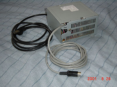
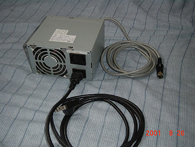
‚³‚Ÿ�A‚¢‚©‚ª‚Å‚·‚©�H�@Ž„‚Í“d‹C�H�ì‚ÍŠµ‚ê‚Ä‚¢‚é‚Ì‚Å�A‚±‚̉ð�à‚ÌŽÊ�^‚ðŽB‚è‚È‚ª‚ç2ŽžŠÔ‚Ù‚Ç‚Å
Š®�¬‚µ‚Ü‚µ‚½‚ª�A“ú� ‚ ‚܂蔼“c‚²‚Ä‚ðˆ¬‚Á‚½Ž–‚Ì‚È‚¢•û‚à�A�T––‚É‚¶‚Á‚‚è�»�삳‚ꂽ‚ç‚¢‚¢‚Æ
Žv‚¢‚Ü‚·�B
�F�X•”•i‚Æ‚©”z�ü�Þ‚ð‚¨Ž�‚¿‚Ì•û‚¾‚Á‚½‚ç�A‚Ù‚Æ‚ñ‚Ç‚½‚¾‚ÅST-7‚ÌAC“dŒ¹‚ªŠ®�¬‚µ‚½‚ÆŽv‚¢‚Ü‚·�B
Ž„‚Í‚±‚ê‚Æ“¯—l‚É�ì‚Á‚½“dŒ¹‚ð2”NˆÈ�ãŽg‚Á‚Ä‚¢‚Ü‚·‚ª‰õ’²‚É–â‘è‚È‚ŠÏ‘ªŽº‚Ì’†‚Å“®�삵‚Ä‚¢‚Ü‚·�B
 In case you hit this
page directly from a Search Engine, you can reach to all of the pages of MAFNET from Top Page
In case you hit this
page directly from a Search Engine, you can reach to all of the pages of MAFNET from Top Page